


26
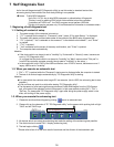
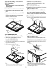
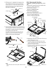
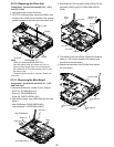
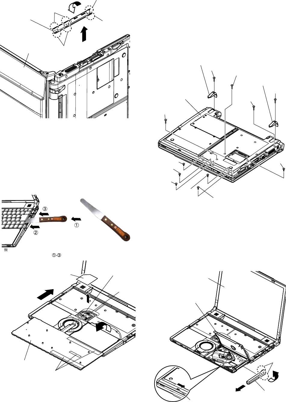
9.2.4. Removing the Top Case
Preparation : perform the section 9.2.1., 9.2.3.
first.
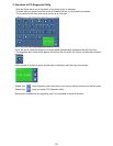
1. Remove the 2 screws (E) and 2 foot rubber backs.
Screw (E) : XTB26+10GFN (N12)
2. Remove the 5 screws (F).
Screw (F) : DXHM0057ZA (N5)
3. Remove the 2 screws (G).
Screw (G) : DXHM0049ZA (N3)
4. Remove the 1 screw (H) and 1 screw (I ).
Screw (H) : DXQT2+D4FNL (N7)
Screw (I ) : DXQT2+E10FNL (N8)
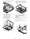
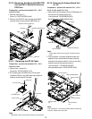
5. KB side cover (L) is adjusted to the upper part as
well as KB side cover (R), the minus clock driver
removes hook (C-1) in the hook position from the
space with the bottom case, rotates to the key-
board side, and detaches.
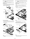
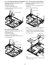
6. The both sides tape pasted to the keyboard bottom
with the spatula is inserted in order of the arrow and
then peel off. It is start-up from the LCD side and
turns inside out on the top case.
The KBD FPC WP sheet is peeld off, FFC (key-
board) is removed from connector (CN25) and
(CN24), and then remove the keyboard.
KB Side Cover (L)
LCD Unit
Hook (C-2)
Hook (C-2)
Hook (C-1)
Hook (C-1)
Keyboard
Both Sides Tape
KBD FPC WP Sheet
CN24
CN25
Spatula
Do not damage the spatula ahead and move a top case in the
direction of the arrow in order.
Note:
KBD-FPC sheet cannot be recycled. Please use new
parts.
Screw (G)
Screw (F)
Screw (I)
Screw (E)
Screw (E)
Foot Rubber Back
Foot Rubber Back
Screw (F)
Screw (G)
Screw (F)
Screw (F)
Screw (H)
Screw (F)
Bottom Case
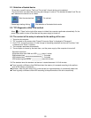
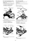
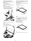
5. Operate the LCD knob and open the LCD Unit to an
angle of 90 degrees or more.
6. The hook 2 places of the disk side cover are re-
moved, and detaches forward while rotating in the
direction of the upper surface.
7. The disk cover lock is mechanically released, and
the disk cover is opened.
Back Side
Disk Side Cove
r
Disk Cover
Mechanical Release Lever
LCD Unit
Hook (D)