32
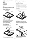
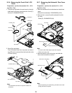
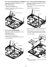
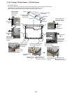
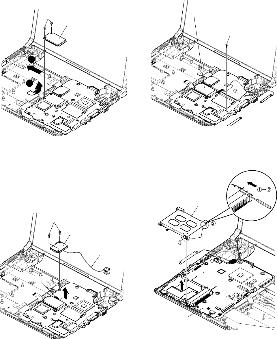
9.2.15. Removing the Wireless LAN Module
Preparation : perform the section 9.2.1., 9.2.3.,
9.2.4. and 9.2.11. first.
1. Remove the 2 screws (X).
Screw (X) : DXQT2+D25FNL (N6)
2. Wireless LAN module is floated in the connector
fulcrum and removed.
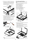
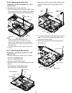
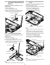
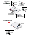
9.2.17. Removing the Card Bus Ejector
Preparation : perform the section 9.2.1., 9.2.3.,
9.2.4. and 9.2.11. first.
1. Remove the 1 screw (Z) from connection side of
wireless LAN.
Screw (Z) : DXQT2+D25FNL (N6)
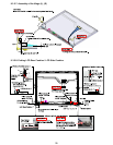
2. Return it on the revers to the card bus ejector side.
3. The minus small driver is inserted in connector
(CN13) and the card bus ejector intuition combina-
tion parts, 2 places of hooks (E). And then remove
the card bus ejector.
Screw (X)
1
2
Wireless LAN Module
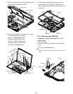
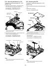
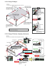
9.2.16. Removing the MODEM
Preparation : perform the section 9.2.1., 9.2.3.,
9.2.4. and 9.2.11. first.
1. Remove the 2 screws (Y).
Screw (Y) : DXQT2+D25FNL (N6)
2. MODEM will be removed from connector (CN17) to
the vertical direction.
Screw (Y)
MODEM
Connector
MODEM Cable
Screw (Z)
Wireless LAN Module
Note :
Be careful not to transform the card bus ejector when
you remove the hook.
Hook (E)
Card Bus Ejector
Main Board


