


50
<FIG2>
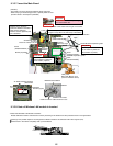
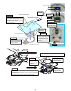
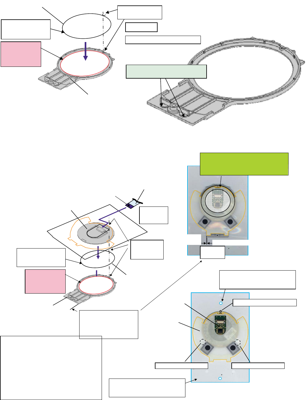
Insertion
after PAD is
pressurized
"NITTO No5000"
Release coated paper
Print side
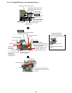
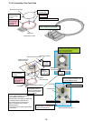
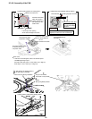
<Preparation for PAD-2>
<FIG:1Preparation for PAD-1>
Touch Pad
Pad WP Sheet
Pad Cover
PAD that has been
prepared is stuck.
Reinforcement board side
Pad FFC is inserted
Thing that doesn’t
begin to be seen
from window of
Pad Cover
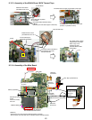
Affixes
Pad Cover Tape
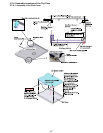
It sticks it
according to
U convex part
Sticking
part externals
Pad Cover Externals
The gap is
0.2 or less
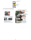
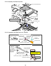
After of two PAD preparation completion
It installs in the pressurizing treatment
device and it pressurizes it.
(Range of shaded portion)
The hole of a transparent mount of
PAD WP SHEET is inserted in the
pin of the treatment device.
PAD position-determining pin
PAD positioning spacerPAD positioning spacer
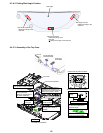
The hole of a transparent mount of
PAD WP SHEET is inserted in the
pin of the treatment device.
Sticking part externals
and externals match of
Pad Case of sticking PAD
that has been prepared.
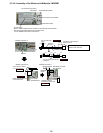
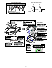
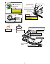
<FIG2>
1. PAD is installed on the treatment device
and it installs it between positioning
the installation three places.
2.The yellowish brown flaking off paper side
of Pad WS Sheet is peeled off and
the positioning hole of a transparent
mount is inserted in the pin of the
treatment device.
3. The sticking part of PAD and WP Sheet is
pressurized.
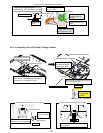
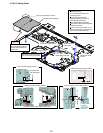
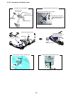
9.3.4.5. Assembly of the Touch Pad
<preparation for PAD>
Affixes Pad Cover Tape
Pad Cover
Thing that doesn’t
begin to be seen
from window of
Pad Cover
Safety work
Division attention of Pad Cover
"NITTO No5000"
Release coated paper
Print side
It sticks it according
to U convex part.
ZA-0 = It is about the hemicycle.
YA-0 = There is no hemicycle.