


43
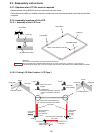
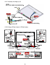
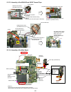
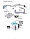
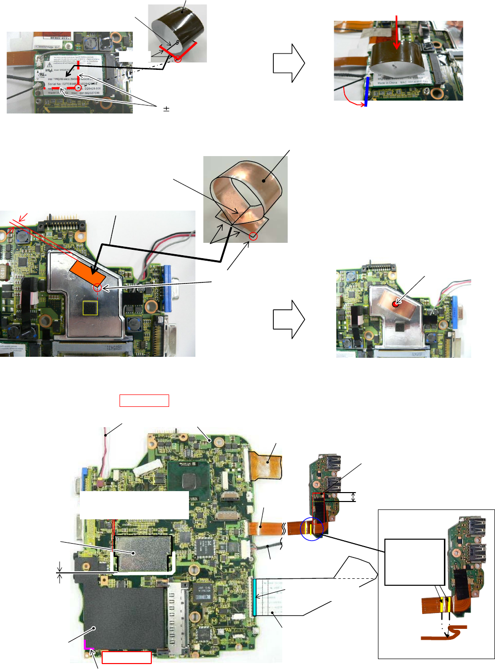
9.3.3.3. Assembly of the WLAN Sheet / MCH Thermal Tape
A two sided tape is peeled
off and affixes
BOX Sheet metal externals suiting
0 1mm
(The line part of the above figure is matched)
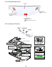
Makes like the incision
part difference all-in roll
Makes like the incision
part difference all-in roll
W-LAN Sheet
MCH Thrmal Tape
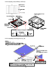
The Sheet center is lightly suppressed by the finger
The Sheet center is lightly
suppressed by the finger.
Processes from rue side to the right under
(Process in parallel to board)
Parallel
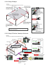
A both sided tape is
peeled off and affixes.
Parallel
The corner part is matched on
the extension line of the
damper externals.
Does not go out of
externals of Heat
Spreader Bottom when
suppressing.
2-5mm
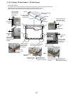
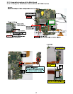
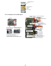
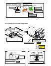
9.3.3.4. Assembly of the Main Board
Main PWB
PCMCIA Sheet
DC-IN Cable
Connection
Memory Spreader
PET Tape (10mmx25mm)
HDD FPC
Connection
USB FPC
Connection
LAN Cable
Connection
FFC Drive
Connection
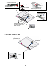
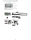
Safety Work
Safety Work
Blue side
(reinforcement board side)
(Attention)
-The board is set in the receiving treatment device and works.
-The connector lock work after FPC is inserted uses the treatment device.
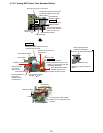
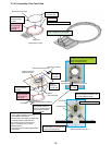
Slit externals match
0-1.5mm
*Does not overlap in the slit.
Slit externals match
0-2mm
*Does not overlap
in the slit.
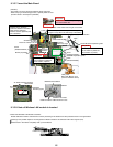
<FIG1>
A line is matched
mutually and Z is
bent by the
standard
Puts according to the silk frame.
The inclination is within 0.5mm.