31
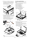
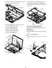
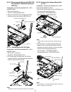
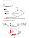
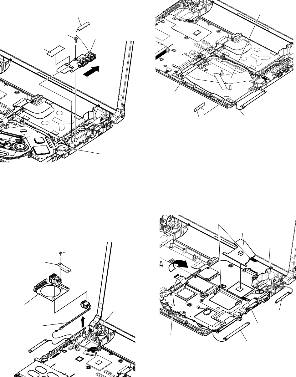
9.2.12. Removing the Bluetooth-USB PCB
Unit (with BT) / Bluetooth Antenna
PCB Unit
Preparation : perform the section 9.2.1., 9.2.3.
and 9.2.4. first.
1. Remove the screw (V).
Screw (V) : DXQT2+D25FNL (N6)
2. Remove the USB FPC from the tape and CN910,
and then remove the bluetooth-USB PCB unit.
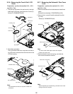
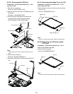
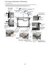
9.2.14.
Removing the Antenna Board Unit
(L), (R)
Preparation : perform the section 9.2.1., 9.2.3.,
9.2.4., 9.2.10. and 9.2.11. first.
1. Peei off the line hold sheet and drive EMI sheet and
then remove the antenna board (R).
Line hold sheet : DFHR3D80ZA (K52)
Drive EMI sheet : DFHE1003ZA (K38)
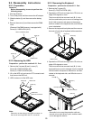
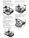
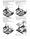
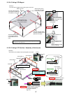
9.2.13 . Removing the DC-IN Cable
Preparation : perform the section 9.2.1., 9.2.3.
and 9.2.4. first.
1. Remove the 1 screw (W) .
Screw (W) : DXQT2+E6FNL (N10)
2. DC-IN jack plate, DC MDM cover, DC-IN cable
connector (CN601), and FAN sheet are peeled off,
and then remove the DC-IN cable.
Screw (V)
USB FPC
Bluetooth Antenna PCB Unit
Tape
Bluetooth-USB PCB Unit
Screw (W)
DC Jack Plate
DC MDM Cover
DC-IN Cable
FAN Sheet
Note:
FAN sheet cannot be recycled. Please use new parts.
Note:
These sheet cannot be recycled. Please use new
parts.
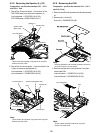
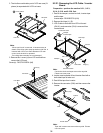
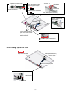
2. Line hold sheet 1 and heat spreader bottom are
peeled off from main Board's wireless LAN side,
and takes the antenna cable (L) out from the ditch
and then remove the antenna board (L).
Line hold sheet 1 : DFHR3D21ZB (K43)
Heat spreader bottom : DFMY3222ZA (K69)
FFC Drive
Line Hold Sheet
Antenna Cable (R)
Drive EMI Sheet
Antenna Cable
(L)
Antenna Board
(L)
Antenna Board
(R)
Antenna Cable
(R)
Heat Spreader Bottom
Line Hold Sheet 1
Line Hold Sheet 1
Note:
Line hold sheet 1 and heat spreader bottom cannot be
recycled. Please use new parts.


