


139
ENGLISH
Glossary/Specifi cations
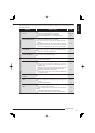
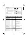
Rated Power Supply .................100 to 240 V AC, 50/60 Hz
Rated Input ...............................0.9- 0.4 A (100-240 V)
Colour System ..........................PAL-type colour system
Operating Temperature .............41 °F-104 °F (5 °C to 40 °C)
Relative Humidity .....................Max. 80 (%)
Altitude .....................................Max. 2000 (m)
Dimensions ...............................425 (Width) x 375 (Depth) x 133 (Height) (mm)
Weight .....................................10.4 kg (when 1 HDD is attached)
11.1 kg (when 2 HDDs are attached)
Recording System ....................Digital recording system
Sampling ............................13.5 MHz
Data Compression .............MPEG4
Compression Unit ...............Frame, Field
Recording Resolution ...............704 x 576, 704 x 288, 352 X 288
Recording Device .....................Hard disk drive (HDD)
Audio Recording System ..........AD-PCM system
Video Input ...............................16 Input BNC-Connectors: 1.0 V(p-p), 75 ohms.
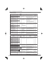
Monitor Output ..........................S-Connector: Y-Signal: 1.0 V(p-p), 75 ohms.
C-Signal: 0.3 V(p-p), 75 ohms.
2 Output BNC-Connectors: 1.0 V(p-p), 75 ohms.
RCA-jack: 1.0 V(p-p), 75 ohms.
XGA
Throughout Output ..................16 Output BNC-Connectors: 1.0 V(p-p), 75 ohms.
Cascade Video Input ................BNC-Connector: 1.0 V(p-p), 75 ohms.
Cascade Video Output .............BNC-Connector: 1.0 V(p-p), 75 ohms.
Audio Input ...............................RCA-Jack: 308 mV(rms), 50 k ohms.
Audio Output ............................RCA-Jack: 308 mV(rms), 1 k ohms.
Clock .....................................±20 seconds/month (when power is supplied, 25 °C)
Timer Program ..........................16 programs-Daily start and stop time for one week x 1 set
Memory Backup .......................Lasts for more than 1 month (when fully charged)
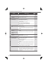
Connectors
External storage terminal ...Serial bus (1-4) (For connecting the recommended optional items only)
Control terminals
Emergency Input ..........Active: When terminals are short-circuited or “Low” Level voltage is applied.
Non active: Open.
EVENT (1-3) ................Active: When terminals are short-circuited or “Low” Level voltage is applied.
Non active: Open.
Mode out (1-4) .............Active: “Low” Level Max. Drive current 30 mA DC.
Non active: Open. Max. Voltage 24 V DC.
Call out +/– ...................Active: Short Max. Drive current 7 mA DC.
(Photo coupler output) Non active: Open. Max. Voltage 24 V DC.
Ground terminal
DC 12 V Output ............Max. 350 mA DC (when Main switch and power button is turned on)
CLOCK ADJ IN ............Active: When terminals are short-circuited or “Low” Level voltage is applied.
Non active: Open.
CLOCK ADJ OUT ........Active: “Low” Level Max. Drive current 30 mA DC.
Non active: Open Max. Voltage 24 V DC.
(CLOCK ADJ OUT is a through output terminal of CLOCK ADJ IN.)
Alarm Input .........................Active: When terminals are short-circuited or “Low” Level voltage is applied.
Non active: Open.
Alarm output .......................Active: “Low” Level Max. Drive current 30 mA DC.
Non active: Open Max. Voltage 24 V DC.
CONT OUT .........................Modular jack 4 pins
RS-485 ...............................Input/Output terminal RJ-45
PTZ terminal .......................RS-232C terminal
RS-422 terminal
Serial port ...........................RS-232C D-SUB 9 pin
Communication
LAN ..............................Connector form: RJ-45 Physical interface: 10BASE-T/100BASE-TX
DVD-R/RW, CD-R/RW recording format ...........Original format
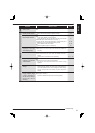
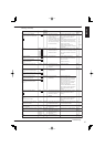
Accessories ..............................AC power cord (For U.K/for the Continent) 2
CD 1
Cable clamping band 2
Installer’s manual (this manual) 1
User’s manual 1
Recording time table 1
Weight and dimensions shown are approximate.
Design and specifi cations are subject to change without notice.
This unit complies with the European EMC test standard EN50130-4.
Specifi cations