


47
Viewing images
ENGLISH
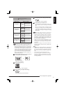
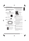
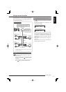
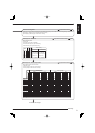
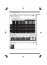
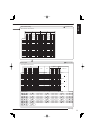
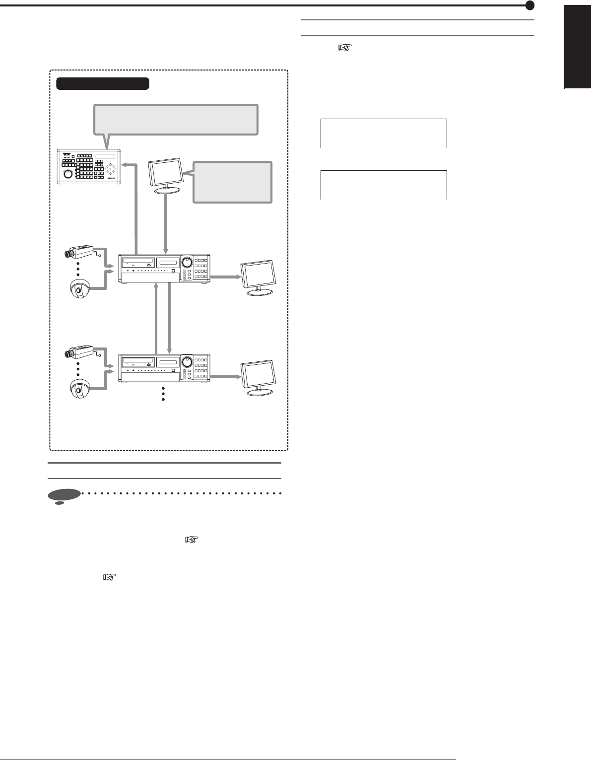
You can connect up to 16 DX-TL5716E, and using the
optional keyboard, you can view images supplied from
all the connected cameras on the master monitor that is
connected to the fi rst recorder.
Camera
(up to 16 cameras)
Camera
(up to 16 cameras)
(up to 16 recorders)
Master monitor
Local monitor
Slave recorder
Slave recorder
Output B
RS-485
Cascade output*
Output B
Local monitor
Configuration example
Keyboard DX-KB5UE
(option)
With the keyboard, you can control the multiplexers
and recorder settings of all the connected recorders
as well as PTZ operation of all the cameras.
You can view images
supplied from all the
connected cameras on
the master monitor.
* : The Cascade output terminal outputs the same image as that from
the OUTPUT A terminal.
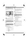
Before using cascade function
Notice
• Check the following.
•
Recorders are connected via RS-485 terminal. Video
terminals are cascaded. (
Page 26 “Cascade
connection”)
•
Each recorder has its own unique ID number from 01
to 16. (
Page 114 “RS-485 cascade setting”)
Using cascade function
Cautions about the cascade function
• See
page 26 and the keyboard’s instruction
manual for cascade connection and operational
procedures.
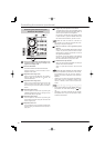
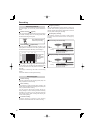
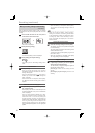
• The status of the cascade mode is displayed on the
LCD of the slave recorder.
01-01-2008 00:00:00
SLAVE ON ID01
<Cascade mode (connecting)>
01-01-2008 00:00:00
SLAVE MODE ID01
<Cascade mode (standby)>
• Even during cascade connection, you can operate
all the connected recorders using the buttons on the
front panel or via communication, however, when
such operation is instructed at the same time as the
operation via the keyboard, the operation instructed
later precedes.
• Images from the cascade output are not output from
the XGA port.
• When you switch the recorder to be operated, the
displayed images may be disturbed.