


21
Beginning
ENGLISH
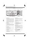
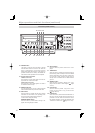
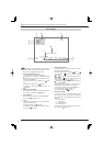
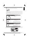
CLOCK ADJ OUT terminal
Terminal to output the signal to set the clocks of other
recorders to the nearest hour (00 minute 00 second) in
sync with input of CLOCK ADJ.
Notice
• The CLOCK ADJ OUT terminal may output the signal
for several seconds when the MAIN switch on the
rear panel of the recorder is turned on or the recorder
recovers from a power failure. When the recorders
are cascade-connected, the clock of the recorder
connected in the next stage may be adjusted.
EVENT terminals (1 to 3)
Input terminals for activate the function confi gured in
the <Event terminal> menu. (
Page 108)
EMERGENCY terminal
Input terminal to start emergency recording forcibly.
MODE OUT terminals (1 to 4)
Output terminals to notify the current recorder sta-
tus. Select the status information to be output in the
<Mode-out • Remaining capacity> menu (
page
107).
Notice
• The MODE OUT terminal may output a signal for
several seconds when the MAIN switch on the rear
panel of the recorder is turned on or the recorder
recovers from a power failure.
CALL OUT (+) terminal / CALL OUT (-) terminal
Output terminal to notify the trouble in the recorder
and its exclusive ground terminal (isolation terminal).
Information to be externally output consists of items
selectable in the <Warning display • Buzzer • Call-out>
menu (
pages 105 and 106) and items to be output
regardless of the menu settings.
Notice
• The CALL OUT terminal may output the signal for
several seconds when the MAIN switch on the rear
panel of the recorder is turned on or the recorder
recovers from a power failure. Pay attention to
this matter if you use peripheral devices to issue
notifi cation.
GND terminal
This terminal is used as common ground terminal.
DC 12V OUT terminal
This terminal outputs the direct voltage only when both
the MAIN switch and the POWER button are on. The
maximum electric current is 350 mA.
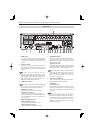
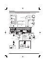
8 GND terminals
This terminal is used as common ground terminal.
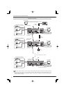
9 PTZ control terminals
These terminals are used to connect a PTZ camera to
control (pan, tilt and zoom) it.
10 CONT OUT connector
Connector to connect optionally available HDD exten-
sion unit DX-ZD6UE. This terminal is used to link the
power supply of this recorder with the HDD extension
unit.
11 RS485 connector
Connector to control this recorder remotely.
12 RS-232C connector
This connector is used to connect a host device
equipped with RS-232C connector (such as a personal
computer). This recorder can be controlled from other
devices via this connector.
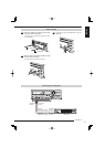
13 VIDEO OUTPUT connectors
OUTPUT A VIDEO connector
BNC connector to output video signals to the monitor.
OUTPUT A S(Y/C) connector
Connector to output brightness signals and color sig-
nals separately for higher picture quality. Signals can
be output from this terminal and the OUTPUT A VIDEO
connector simultaneously.
OUTPUT B VIDEO connector
BNC connector to output video signals to the second (B)
monitor. (
Page 24)
14 SERIAL BUS ports
Input and output ports to connect a device equipped
with serial bus terminal. Don't use the function to con-
trol the powers of external devices using the bus power
of this recorder. Bus power cannot be used.
By connecting external HDDs to this recorder, you can
expand the memory or use them as a copy device.
However, when you perform recording, playback, or
copy at a high rate using this recorder, recording or
playback data dropout or other failure may occur be-
cause of slow data transfer or slow response. Be sure
to check for such failure before starting the practical
operation of the recorder.
15 RESET button
When this button is pressed, this recorder is reset and
the power is turned off. In this case, image data, menu
settings, and the clock setting are retained.
16 LAN port
Port for communication with the special application
software using a web browser.
17 XGA port
Port to output video signals to XGA monitor.
18 AUDIO connectors
AUDIO IN connector (1 to 2)
RCA connector to input audio signals.
AUDIO OUT connector
RCA connector to output audio signals. The audio of
the selected channel is output.