


119
Operation selection function parameters
2
FUNCTIONS
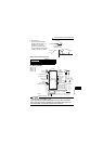
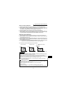
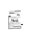
<Set point input calibration>
1. Apply the input voltage of 0% set point setting (e.g. 0V) across terminals 2-5.
2. Make calibration using the calibration parameters C2, C3. At this time, enter in C2
the frequency which should be output by the inverter at the deviation of 0% (e.g.
0Hz). (When using the FR-PU04, make calibration with Pr. 902.)
3. Apply the voltage of 100% set point (e.g. 5V) to across terminals 2-5.
4. Make calibration using Pr. 38 and calibration parameter C4. At this time, enter in Pr.
38 the frequency which should be output by the inverter at the deviation of 100%
(e.g. 60Hz). (When using the FR-PU04, make calibration with Pr. 903.)
<Detector output calibration>
1. Apply the output current of 0% detector setting (e.g. 4mA) across terminals 4-5.
2. Make calibration using the calibration parameter C6. (When using the FR-PU04,
make calibration with Pr. 904.)
3. Apply the output current of 100% detector setting (e.g. 20mA) across terminals 4-5.
4. Make calibration using the calibration parameter C7. (When using the FR-PU04,
make calibration with Pr. 905.)
Note: The frequencies set in the calibration parameter C5 and Pr. 39 should be equal
to those set in the calibration parameter C2 and Pr. 38, respectively.
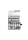
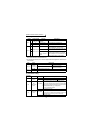
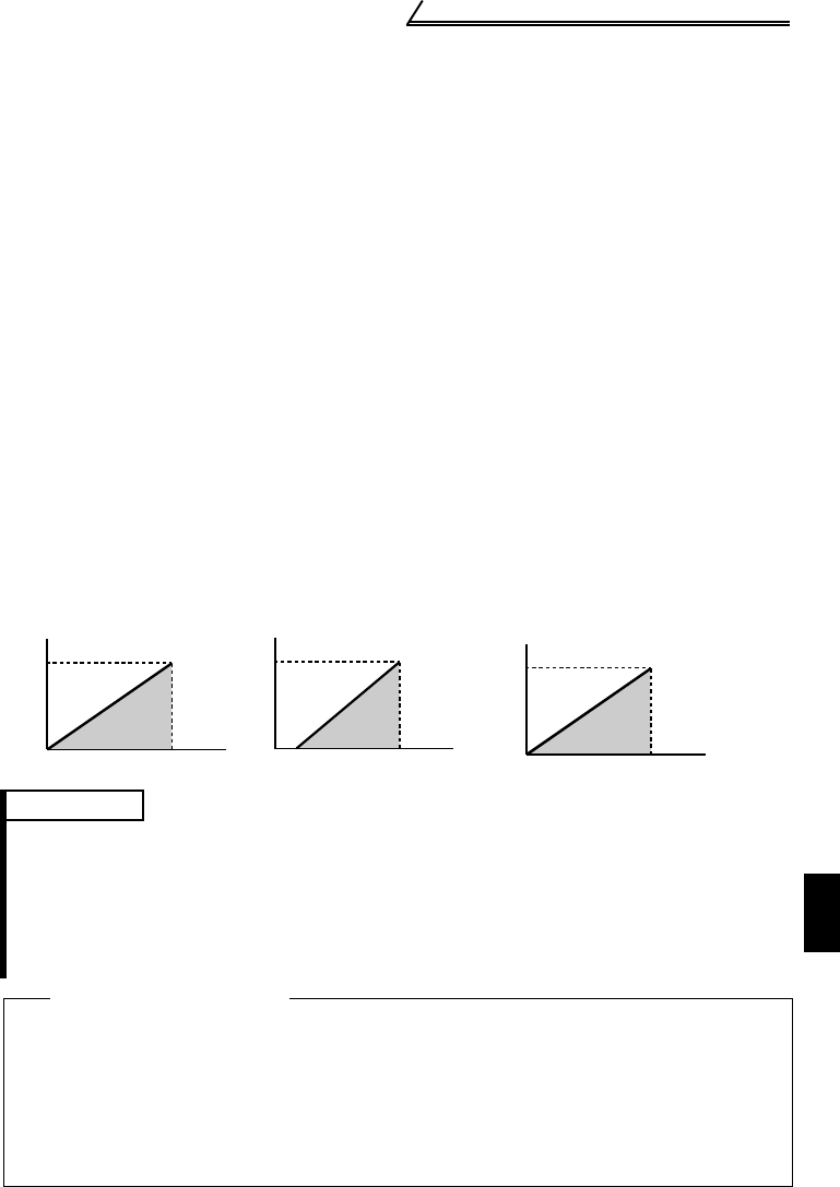
The results of the above calibration are as shown below:
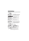
REMARKS
•If the multi-speed (RH, RM, RL signal) or jog operation (JOG signal) is entered, PID control is
stopped and multi-speed or jog operation is started.
•When the terminal functions are changed using Pr. 60 to Pr. 65, the other functions may be
affected. Confirm the functions of the corresponding terminals before making settings.
•When PID control is selected, the minimum frequency is the frequency set in the calibration
parameter C2 and the maximum frequency is the frequency set in Pr. 38.
(The Pr. 1 "maximum frequency" and Pr. 2 "minimum frequency" settings are also valid.)
♦Related parameters♦
• X14 signal assignment ⇒ Pr. 60 to Pr. 63 (input terminal function selection) (refer to page 98)
• FUP, FDN and RL signal assignment ⇒ Pr. 64 "RUN terminal function selection", Pr. 65 "A, B, C
terminal function selection" (refer to page 100)
• Voltage input selection (0 to ±5V, 0 to ±10V) ⇒ Pr. 73 "0-5V/0-10V selection"
(refer to page 104)
• Operation mode selection ⇒ Pr. 79 "operation mode selection" (refer to page 109)
• Making terminal calibration ⇒ Pr. 38, Pr. 39, C2 to C7 (calibration parameters) (refer to page 82)
100
0
0
5
(
V
)
(%)
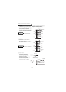
[Set point setting]
0
0
20
(
mA
)
4
[Detection value]
(%)
100
[Manipulated variable]
0
0
100 Deviation (%)
Manipulated
variable (Hz)
60