


23
How to use the control circuit terminals
1
WIRING
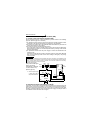
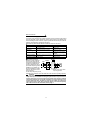
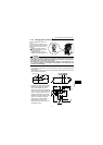
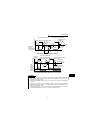
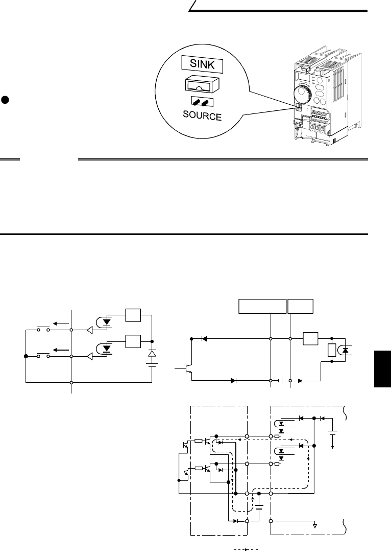
1.3.3 Changing the control logic
The input signals are set to sink
logic.
To change the control logic, the
jumper connector under the setting
dial must be moved to the other
position.
Change the jumper connector
position using tweezers, a pair of
long-nose pliers etc.
Change the jumper connector
position before switching power on.
CAUTION
•Make sure that the front cover is installed securely.
•The front cover is fitted with the capacity plate and the inverter unit with the
rating plate. Since these plates have the same serial numbers, always replace
the removed cover onto the original inverter.
•The sink-source logic change-over jumper connector must be fitted in only
one of those positions. If it is fitted in both positions at the same time, the
inverter may be damaged.
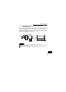
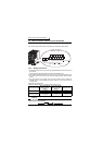
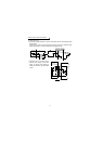
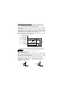
1) Sink logic type
• In this logic, a signal switches on when a current flows from the corresponding signal
input terminal.
Terminal SD is common to the contact input signals. Terminal SE is common to the
open collector output signals.
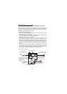
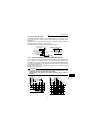
• Connecting a positive terminal of the
external power supply for transistor
output to terminal PC prevents a
malfunction caused by an undesirable
current. (Do not connect terminal SD
of the inverter with terminal 0V of the
external power supply. When using
terminals PC-SD as a 24VDC power
supply, do not install an external
power supply in parallel with the
inverter. Doing so may cause a
malfunction in the inverter due to an
undesirable current.)
AX40Inverter
SE
RUN
24VDC
Power supply
STR
STF
SD
1
9
R
R
R
R
1
2
9
10
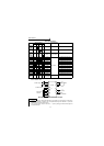
24VDC SD
PC
STR
STF
Inverter
24VDC
(SD)
9
Current flow
AY40
transistor
output module