27
Input terminals
1
WIRING
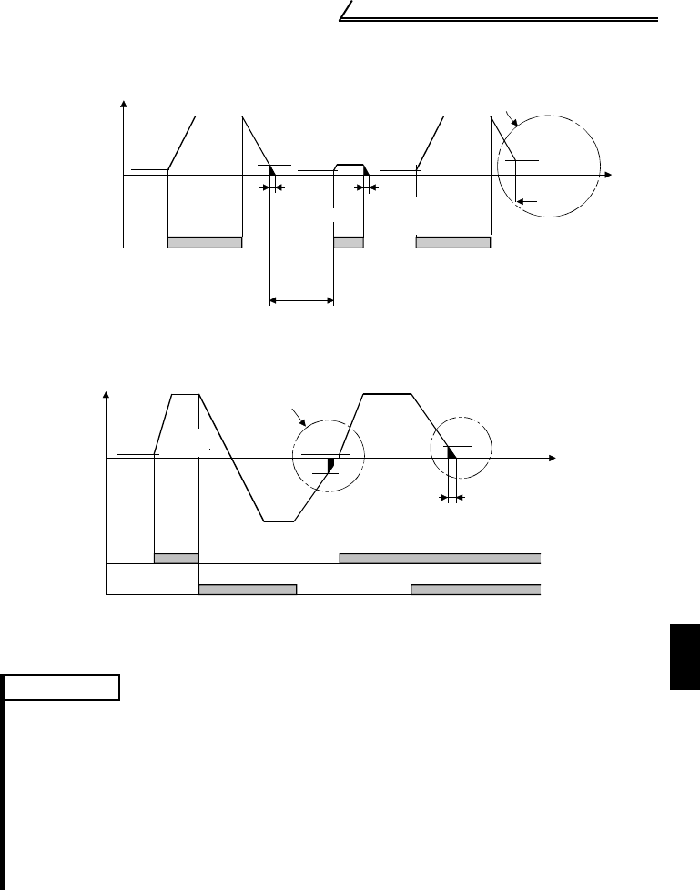
Start/Stop Timing Chart (for two-wire type)
Forward-Reverse Rotation Switch-Over Timing Chart
REMARKS
*1. The "starting frequency" in Pr. 13 (factory-set to 0.5Hz) may be set between 0 and 60Hz.
*2. If the next start signal is given during DC injection brake operation, the DC injection brake
is disabled and restart is made.
*3. The "DC injection brake operation time" in Pr. 11 (factory-set to 0.5s) may be set between
0 and 10s.
*4. The frequency at which the motor is coasted to a stop is not more than the "DC injection
brake operation frequency" set in Pr. 10 (factory setting = 3Hz; may be set between 0 and
120Hz) or not more than 0.5Hz.
*5. The "starting frequency" in Pr. 13, "DC injection brake operation time" in Pr. 11 and "DC
injection brake operation frequency" in Pr. 10 are the factory-set values.
DC injection
brake operation
time Pr. 11
Output frequency
Starting frequency
Pr.13
(*1)
0.5Hz
ON
DC injection brake
operation
frequency Pr. 10
3Hz
0.5s
DC injection
brake operation
time Pr. 11
0.5Hz
0.5s
ON
0.5Hz
ON
3Hz
Coasted to
a stop
Time
DC injection brake
not operated
DC injection brake disabledDC injection brake enabled
Start signal
terminal
(*4)
(*3)
(*3)
(*2)
Across STF-SD
Across STR-SD
Output frequency
Starting
frequency
Pr.13
(*1)
0.5Hz
Forward
rotation
Forward
rotation
3Hz
3Hz
Start signal switched on
while DC injection brake
is being operated
DC injection brake operation
frequency Pr. 10
DC injection
brake enabled
Time
DC injection brake
operation time Pr. 11
0.5s
ON
ON ON
ON
Reverse
rotation
0.5Hz
Start
signal
terminal
(*3)
(*4)
Across
STF-SD
Across
STR-SD


