


149
CHAPTER 6 PORT FUNCTIONS
P-ch
WR
PM
WR
PORT
RD
WR
PUO
V
DD
Selector
PUO13
Output Latch
(P130 and P131)
PM130, PM131
Internal bus
P130/ANO0,
P131/ANO1
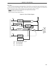
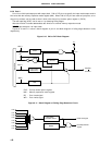
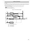
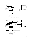
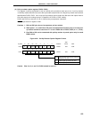
6.2.11 Port 13
This is a 2-bit input/output port with output latches. Input mode/output mode can be specified bit-wise by means
of port mode register 13 (PM13). When pins P130 and P131 are used as input port pins, an on-chip pull-up resistor
can be used as a 2-bit unit by means of pull-up resistor option register H (PUOH).
Alternate function includes D/A converter analog output.
RESET input sets the input mode.
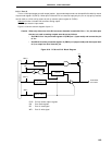
Figure 6-18 shows a block diagram of port 13.
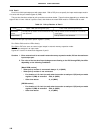
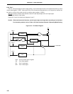
Caution When only either one of the D/A converter channels is used with AV
REF1< VDD, the other pins
that are not used as analog outputs must be set as follows:
• Set PM13. bit of the port mode register 13 (PM13) to 1 (input mode) and connect the pin
to V
SS.
• Set PM13x bit of the port mode register 13 (PM13) to 0 (output mode) and the output latch
to 0, to output low level from the pin.
Figure 6-18. P130 and P131 Block Diagram
PUO : Pull-up resistor option register
PM : Port mode register
RD : Port 13 read signal
WR : Port 13 write signal