


186
CHAPTER 8 16-BIT TIMER/EVENT COUNTER
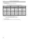
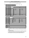
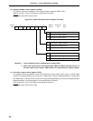
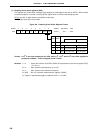
(3) Capture/compare control register 0 (CRC0)
This register controls the operation of the capture/compare registers (CR00, CR01).
CRC0 is set with a 1-bit or 8-bit memory manipulation instruction.
RESET input sets CRC0 value to 04H.
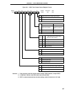
Figure 8-5. Capture/Compare Control Register 0 Format
0000
0 CRC02 CRC01 CRC00
76543210Symbol
CRC0
FF4CH 04H R/W
Address After Reset R/W
CRC00
CR00 Operating Mode Selection
0
Operates as compare register
1
Operates as capture register
CRC01
CR00 Capture Trigger Selection
Captures on valid edge of TI01
Captures on valid edge of TI00
0
1
CRC02
CR01 Operating Mode Selection
Operates as compare register
Operates as capture register
0
1
Cautions 1. Timer operation must be stopped before setting CRC0.
2. When clear & start mode on a match between TM0 and CR00 is selected with the 16-
bit timer mode control register, CR00 should not be specified as a capture register.
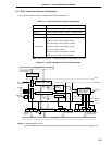
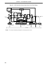
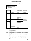
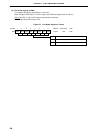
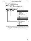
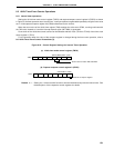
(4) 16-bit timer output control register (TOC0)
This register controls the operation of the 16-bit timer/event counter output control circuit. It sets R-S type
flip-flop (LV0) setting/resetting, the active level in PWM mode, inversion enabling/disabling in modes other
than PWM mode, 16-bit timer/event counter timer output enabling/disabling, one-shot pulse output operation
enabling/disabling, and output trigger for a one-shop pulse by software.
TOC0 is set with a 1-bit or 8-bit memory manipulation instruction.
RESET input sets TOC0 value to 00H.