


285
CHAPTER 15 D/A CONVERTER
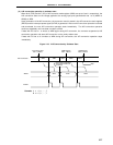
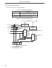
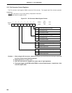
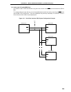
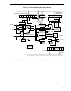
15.4 Operations of D/A Converter
(1) Select the channel 0 operating mode and channel 1 operating mode by DAM4 and DAM5 of D/A converter
mode register (DAM), respectively.
(2) Set the data corresponding to the analog voltages output to the ANO0/P130 and ANO1/P131 pins to the
D/A conversion value setting registers 0 and 1 (DACS0 and DACS1), respectively.
(3) The channel 0 and channel 1 D/A conversion operations can be started by setting DACE0 and DACE1 of the
DAM, respectively.
(4) In the normal mode, the analog voltage signals are output to the ANO0/P130 and ANO1/P131 pins immediately
after the D/A conversion. In the real-time output mode, the analog voltage signals are output synchronously
with the output triggers.
(5) In the normal mode, the analog voltage signals to be output are held until new data are set in DACS0 and
DACS1. In the realtime output mode, new data are set in DACS0 and DACS1 and then they are held until
the next trigger is generated.
Caution Set DACE0 and DACE1 after setting data in DACS0 and DACS1.