


342
CHAPTER 17 SERIAL INTERFACE CHANNEL 0 (
µ
PD78054Y Subseries)
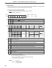
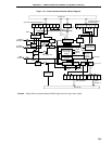
17.1 Serial Interface Channel 0 Functions
Serial interface channel 0 employs the following four modes.
• Operation stop mode
• 3-wire serial I/O mode
• 2-wire serial I/O mode
•I
2
C (Inter IC) bus mode
Caution Do not switch the operation mode (3-wire serial I/O, 2-wire serial I/O, I
2
C bus) while the
operation of serial interface channel 0 is enabled. Stop the serial operation before switching
the operation mode.
(1) Operation stop mode
This mode is used when serial transfer is not carried out. Power consumption can be reduced.
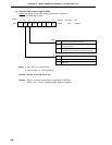
(2) 3-wire serial I/O mode (MSB-/LSB-first selectable)
This mode is used for 8-bit data transfer using three lines, one each for serial clock (SCK0), serial output (SO0)
and serial input (SI0). This mode enables simultaneous transmission/reception and therefore reduces the data
transfer processing time.
The start bit of transferred 8-bit data is switchable between MSB and LSB, so that devices can be connected
regardless of their start bit recognition.
This mode should be used when connecting with peripheral I/O devices or display controllers which incorporate
a conventional synchronous clocked serial interface as is the case with the 75X/XL, 78K, and 17K series.
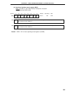
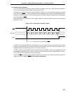
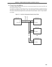
(3) 2-wire serial I/O mode (MSB-first)
This mode is used for 8-bit data transfer using two lines of serial clock (SCK0) and serial data bus (SB0 or
SB1).
This mode enables to cope with any one of the possible data transfer formats by controlling the SCK0 level
and the SB0 or SB1 output level. Thus, the handshake line previously necessary for connection of two or
more devices can be removed, resulting in the increased number of available input/output ports.