


273
CHAPTER 14 A/D CONVERTER
14.4 A/D Converter Operations
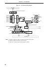
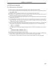
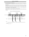
14.4.1 Basic operations of A/D converter
(1) Set the number of analog input channels with A/D converter input select register (ADIS).
(2) From among the analog input channels set with ADIS, select one channel for A/D conversion with A/D converter
mode register (ADM).
(3) Sample & hold circuit samples the voltage input to the selected analog input channel.
(4) Sampling for the specified period of time sets the sample & hold circuit to the hold state so that the circuit
holds the input analog voltage until termination of A/D conversion.
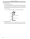
(5) Bit 7 of the successive approximation register (SAR) is set and the tap selector sets the series resistor string
voltage tap to (1/2) AV
REF0.
(6) The voltage difference between the series resistor string voltage tap and analog input is compared with a
voltage comparator. If the analog input is greater than (1/2) AVREF0, the MSB of SAR remains set. If the input
is smaller than (1/2) AV
REF0, the MSB is reset.
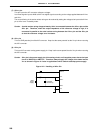
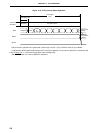
(7) Next, bit 6 of SAR is automatically set and the operation proceeds to the next comparison. In this case, the
series resistor string voltage tap is selected according to the preset value of bit 7 as described below.
• Bit 7 = 1 : (3/4) AV
REF0
• Bit 7 = 0 : (1/4) AVREF0
The voltage tap and analog input voltage are compared and bit 6 of SAR is manipulated with the result as
follows.
• Analog input voltage ≥ Voltage tap : Bit 6 = 1
• Analog input voltage < Voltage tap : Bit 6 = 0
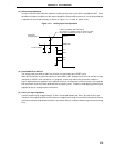
(8) Comparison of this sort continues up to bit 0 of SAR.
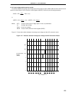
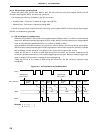
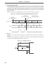
(9) Upon completion of the comparison of 8 bits, any effective digital resultant value remains in SAR and the
resultant value is transferred to and latched in the A/D conversion result register (ADCR).
At the same time, the A/D conversion termination interrupt request (INTAD) can also be generated.