


179
CHAPTER 8 16-BIT TIMER/EVENT COUNTER
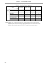
8.3 16-Bit Timer/Event Counter Configuration
The 16-bit timer/event counter consists of the following hardware.
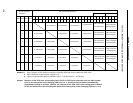
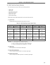
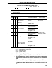
Table 8-4. 16-Bit Timer/Event Counter Configuration
Item Configuration
Timer register 16 bits × 1 (TM0)
Register Capture/compare register: 16 bits × 2 (CR00, CR01)
Timer output 1 (TO0)
Timer clock select register 0 (TCL0)
16-bit timer mode control register (TMC0)
Capture/compare control register 0 (CRC0)
Control register 16-bit timer output control register (TOC0)
Port mode register 3 (PM3)
External interrupt mode register 0 (INTM0)
Sampling clock select register (SCS)
Note
Note Refer to Figure 21-1. Basic Configuration of Interrupt Function.
TCL06 TCL05
TCL04
Timer Clock
Selection
Register 0
3
Internal bus
Capture/Compare
Control Register 0
CRC02 CRC01
CRC00
Selector
TI01/
P01/INTP1
INTTM3
2f
XX
f
XX
f
XX
/2
f
XX
/2
2
Selector
16-Bit Capture/Compare
Control Register (CR01)
Internal Bus
16-Bit Capture/Compare
Control Register (CR00)
Clear
Match
Clear Circuit
TMC03 TMC02 TMC01
OVF0
OSPTOSPETOC04
LVS0
LVR0TOC01 TOE0
16-Bit Timer Mode
Control Register
16-Bit Timer Output
Control Register
2
PWM Pulse
Output
Controller
16-Bit Timer/Event
Counter Output
Control Circuit
Note 2
TMC01-TMC03
INTP0
INTTM01
TO0/P30
INTP1
INTTM00
Match
TMC01-TMC03
3
16-Bit Timer Register (TM0)
TI00/P00/
INTP0
Note 1
CRC02
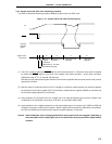
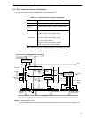
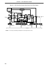
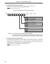
Figure 8-1. 16-Bit Timer/Event Counter Block Diagram
Notes 1. Edge detection circuit
2. The configuration of the 16-bit timer/event counter output control circuit is shown in Figure 8-2.