


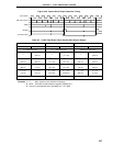
203
CHAPTER 8 16-BIT TIMER/EVENT COUNTER
CRC0 11100000
CRC00CRC01CRC02
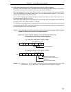
CR00 set as capture register
Captured in CR00 on invalid
edge of TI00/P00 Pin
CR01 set as capture register
TMC0 00/1010000
OVF0
TMC01TMC02TMC03
Clear & start with valid edge of TI00/P00 pin
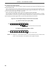
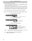
(4) Pulse width measurement by means of restart
When input of a valid edge to the TI00/P00 pin is detected, the count value of the 16-bit timer register (TM0)
is taken into 16-bit capture/compare register 01 (CR01), and then the pulse width of the signal input to the
TI00/P00 pin is measured by clearing TM0 and restarting the count (see register settings in Figure 8-24).
The edge specification can be selected from two types, rising and falling edges by external interrupt mode
register 0 (INTM0) bits 2 and 3 (ES10 and ES11).
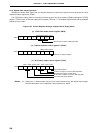
In a valid edge detection, the sampling is performed by a cycle selected by the sampling clock selection register
(SCS), and a capture operation is only performed when a valid level is detected twice, thus eliminating noise
with a short pulse width.
Caution If the valid edge of TI00/P00 is specified to be both rising and falling edge, the 16-bit capture/
compare register 00 (CR00) cannot perform the capture operation.
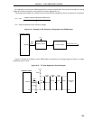
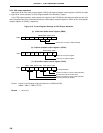
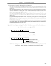
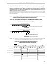
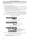
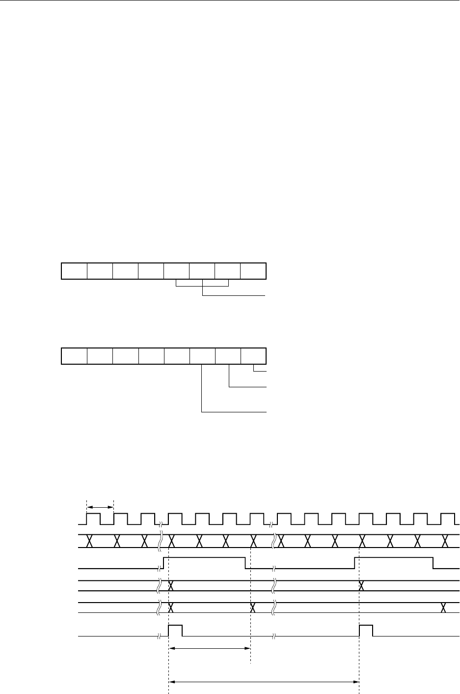
Figure 8-24. Control Register Settings for Pulse Width Measurement by Means of Restart
(a) 16-bit timer mode control register (TMC0)
(b) Capture/compare control register 0 (CRC0)
Remark 0/1: Setting 0 or 1 allows another function to be used simultaneously with pulse width
measurement. See the description of the respective control registers for details.
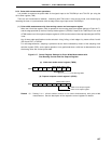
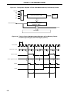
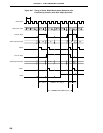
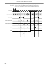
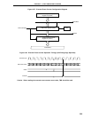
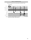
Figure 8-25. Timing of Pulse Width Measurement Operation by
Means of Restart (with Rising Edge Specified)
Count Clock
TM0 Count Value
TI00 Pin Input
CR01 Captured Value
CR00 Captured Value
INTP0
t
0000 0001 D0 0000 0001 D1 00010000D2
D0 D2
D1
D1 × t
D2 × t