


270
CHAPTER 14 A/D CONVERTER
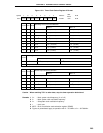
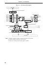
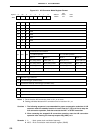
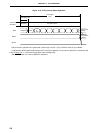
Figure 14-3. A/D Converter Mode Register Format
Notes 1. Set so that the A/D conversion time is 19.1
µ
s or more.
2. Setting prohibited because A/D conversion time is less than 19.1
µ
s.
Cautions 1. The following sequence is recommended for power consumption reduction of A/D
converter when the standby function is used: Clear bit 7 (CS) to 0 first to stop the
A/D conversion operation, and then execute the HALT or STOP instruction.
2. When restarting the stopped A/D conversion operation, start the A/D conversion
operation after clearing the interrupt request flag (ADIF) to 0.
Remarks 1. f
X : Main system clock oscillation frequency
2. MCS : Bit 0 of oscillation mode selection register (OSMS)
CS
<7>
TRG
<6>
FR1 FR0
4
ADM3
3210
FF80H
Address
ADM
Symbol
ADM2 ADM1 HSC
5
01H
After
Reset
R/W
R/W
ADM3
0
0
0
0
1
1
1
1
ADM2
0
0
1
1
0
0
1
1
ADM1
0
1
0
1
0
1
0
1
Analog Input Channel Selection
ANI0
ANI1
ANI2
ANI3
ANI4
ANI5
ANI6
ANI7
TRG
0
1
External Trigger Selection
No external trigger (software starts)
Conversion started by external trigger (hardware starts)
FR1
0
0
1
1
FR0
0
1
0
0
Other than above
A/D Conversion Time Selection
Note 1
f
X
= 5.0 MHz Operation
MCS = 1
80/f
X
(
Setting prohibited
Note 2
)
40/f
X
(
Setting prohibited
Note 2
)
50/f
X
(
Setting prohibited
Note 2
)
100/f
X
(20.0 s)
Setting prohibited
µ
MCS = 0
160/f
X
(32.0 s)
80/f
X
(
Setting prohibited
Note 2
)
100/f
X
(20.0 s)
200/f
X
(40.0 s)
f
X
= 4.19 MHz Operation
MCS = 1
80/f
X
(19.1 s)
40/f
X
(
Setting prohibited
Note 2
)
50/f
X
(
Setting prohibited
Note 2
)
100/f
X
(23.8 s)
MCS = 0
160/f
X
(38.1 s)
80/f
X
(19.1 s)
100/f
X
(23.8 s)
200/f
X
(47.7 s)
µ
µ
µ
µ
µ
µ
µ
CS
0
1
A/D Conversion Operation Control
Operation stop
Operation start
HSC
1
1
0
1
µ
µ