


347
CHAPTER 17 SERIAL INTERFACE CHANNEL 0 (
µ
PD78054Y Subseries)
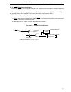
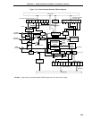
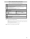
(6) Interrupt request signal generator
This circuit controls interrupt request signal generation. It generates interrupt request signals according to
the settings of interrupt timing specification register (SINT) bits 0 and 1 (WAT0, WAT1) and serial operation
mode register 0 (CSIM0) bit 5 (WUP), as shown in Table 17-3.
(7) Acknowledge output circuit and stop condition/start condition/acknowledge detector
These two circuits output and detect various control signals in the I
2
C mode.
These do not operate in the 3-wire serial I/O mode and 2-wire serial I/O mode.
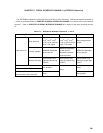
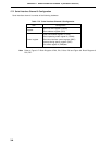
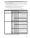
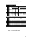
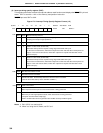
Table 17-3. Serial Interface Channel 0 Interrupt Request Signal Generation
Serial Transfer mode
BSYE WUP WAT1 WAT0 ACKE
Description
3-wire or 2-wire serial I/O mode 0 0 0 0 0 An interrupt request signal is generated each
time 8 serial clocks are counted.
Other than above Setting prohibited
I
2
C bus mode (transmit) 0 0 1 0 0 An interrupt request signal is generated each
time 8 serial clocks are counted (8-clock wait).
Normally, during transmission the settings WAT21,
WAT0 = 1, 0, are not used. They are used only
when wanting to coordinate receive time and
processing systematically using software. ACK
information is generated by the receiving side,
thus ACKE should be set to 0 (disable).
1 1 0 An interrupt request signal is generated each
time 9 serial clocks are counted (9-clock wait).
ACK information is generated by the receiving
side, thus ACKE should be set to 0 (disable).
Other than above Setting prohibited
I
2
C bus mode (receive) 1 0 1 0 0 An interrupt request signal is generated each
time 8 serial clocks are counted (8-clock wait).
ACK information is output by manipulating ACKT
by software after an interrupt is generated.
1 1 0/1 An interrupt request signal is generated each
time 9 serial clocks are counted (9-clock wait).
To automatically generate ACK information,
preset ACKE to 1 before transfer start. However,
in the case of the master, set ACKE to 0
(disable) before receiving the last data.
1 1 1 1 1 After address is received, if the values of the
serial I/O shift register 0 (SI00) and the slave
address register (SVA) match, and if the stop
condition is detected, an interrupt request signal
is generated.
To automatically generate ACK information,
preset ACKE to 1 (enable) before transfer start.
Other than above Setting prohibited
Remark BSYE: Bit 7 of serial bus interface control register (SBIC)
ACKE: Bit 5 of serial bus interface control register (SBIC)