


iR1200 Modem
16 nextel.com
iR1200
IGNITION
POWER
IGNITION
BYPASS
PLUG
120VAC
POWER
SUPPLY
MODEM
ANTENNA
GPS ANTENNA
(OPTIONAL)
COMPUTER
RS-232
GPS DATA
RS-232
MODEM DATA
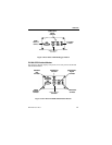
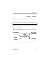
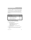
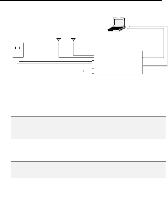
Figure 5 – Cabling Diagram (Fixed Environment)
NOTE: DCE (data communication equipment) refers to your iR1200
Modem
DTE (data terminal equipment) refers to your computer or
mobile device.
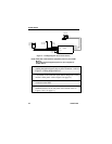
1 Make sure that there is no power being supplied to the modem
(unplug the ignition bypass plug or power connector – refer to
Figure 5 – Cabling Diagram above).
2 Connect the DB-9-P (male) connector on the cable to the DB-
9-S (female) to the connector DCE (labeled Diagnostic on the
modem’s front panel –refer to Figure 4 on page 15).
3 Connect the DB-9-P connector on the cable to the DB-9-S
connector on the DTE.
4 Connect the modem antenna cable to the connector labeled
MODEM antenna on the rear panel of the modem (refer to
Figures 2 and 3 on page 11).