7. Operation and Maintenance
7-8
September 2002 9128-A2-GB20-80
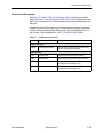
LED Descriptions
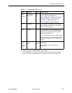
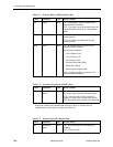
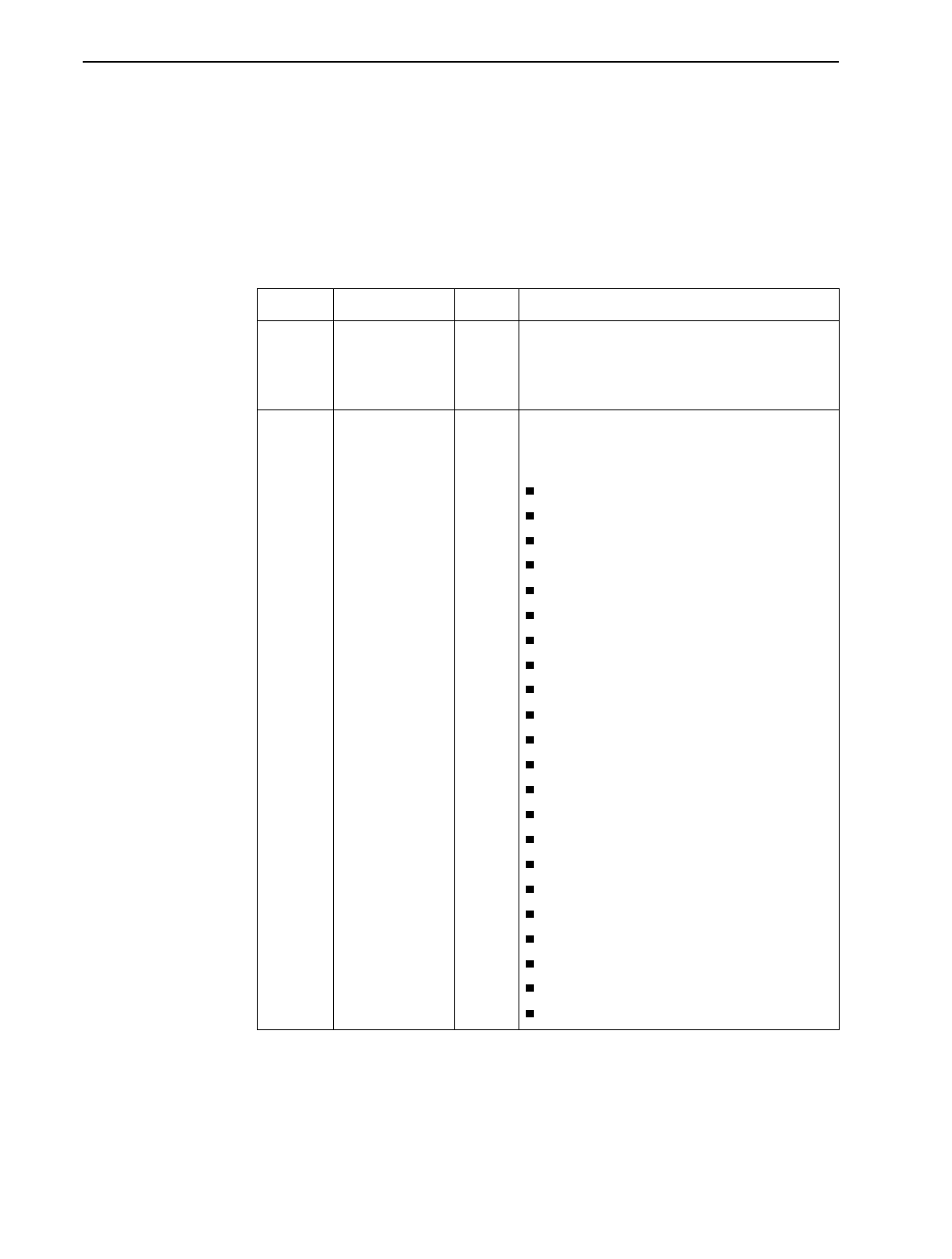
Table 7-1, General Status LEDs, identifies the alarms that cause the Alarm LED to
light. See Table 7-2, Network, DSX, or PRI Interface LEDs, for network, DSX-1,
and PRI interface LED information, Table 7-3, User Data Port LED (CSU/DSUs
Only), for user data port interface LED information, and Table 7-4, Ethernet Port
LED (Routers Only) for Ethernet interface LED information.
Table 7-1. General Status LEDs (1 of 2)
Label Indiction Color What It Means
OK
1
Power and
Operational
Status
Green ON – FrameSaver unit has power and it is
operational.
OFF – FrameSaver unit is in a power-on
self-test, or there is a failure.
ALM Operational
Alarm (Fail)
Red ON – FrameSaver unit has just been reset, or an
error or fault has been detected.
Error/fault/alarm conditions:
Alarm Indication Signal (AIS)
CTS Down
DBM BRI Card Failure
DBM Download Failed
DLCI Down
DTR Down
Ethernet Link Down
Exceeded Error Rate (EER)
Internal Modem Failed
ISDN Network Failed
LMI Down
Loss of Signal (LOS)
Network Communication Link Down
Out of Frame (OOF)
Power Supply/Fan Failure
Primary or Secondary Clock Failed
Self-Test Failed
SLV Latency Exceeded
SLV Timeout
Suboptimal Link Rate
Two Level-1 Users Accessing Device
Yellow Alarm Signal
1
When an ISDN BRI DBM is installed, if the OK LED comes on then goes off during
power recycling, the ISDN BRI DBM may have failed.
2
On the Display LEDs & Control Leads screen for the Model 9128-II only, FR Mode
is On or Off. When On (highlighted), the FrameSaver unit is in Frame Relay mode.


