E. Connectors, Cables, and Pin Assignments
9128-A2-GB20-80 September 2002
E-17
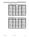
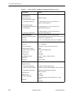
Modem Connector
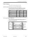
The dial modem interface/connector that is integrated into the FrameSaver unit is
an RJ11 6-position, 4-contact unkeyed modular jack. The following table shows pin
assignments and the purpose of each.
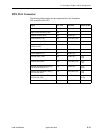
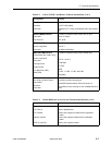
ISDN DBM Connector
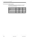
The backup connection is through the DBM interface/connector, which is an
8-position keyed modular jack. The following tables show pin assignments for the
ISDN PRI and BRI DBMs and the purpose of each.
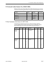
FrameSaver SLV 9128-II ISDN PRI pin assignments:
FrameSaver SLV 9126 ISDN BRI/U pin assignments:
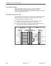
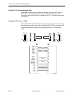
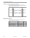
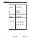
ISDN Modular Cable
The ISDN cable comes with the FrameSaver unit ordered with the DBM feature.
Function Circuit Direction Pin Number
Ring R To Local Loop 2
Tip T To Local Loop 3
Function Circuit Direction Pin Number
PRI Receive Ring DBM1 From Local Loop 1
PRI Receive Tip DBM2 From Local Loop 2
PRI Transmit Ring DBM4 To Local Loop 4
PRI Transmit Tip DBM5 To Local Loop 5
Function Circuit Direction Pin Number
BRI Transmit/Receive Ring DBM4 To/From
Local Loop
4
BRI Transmit/Receive Tip DBM5 To/From
Local Loop
5


