4. Configuration Options
4-50
September 2002 9128-A2-GB20-80
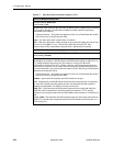
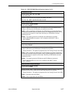
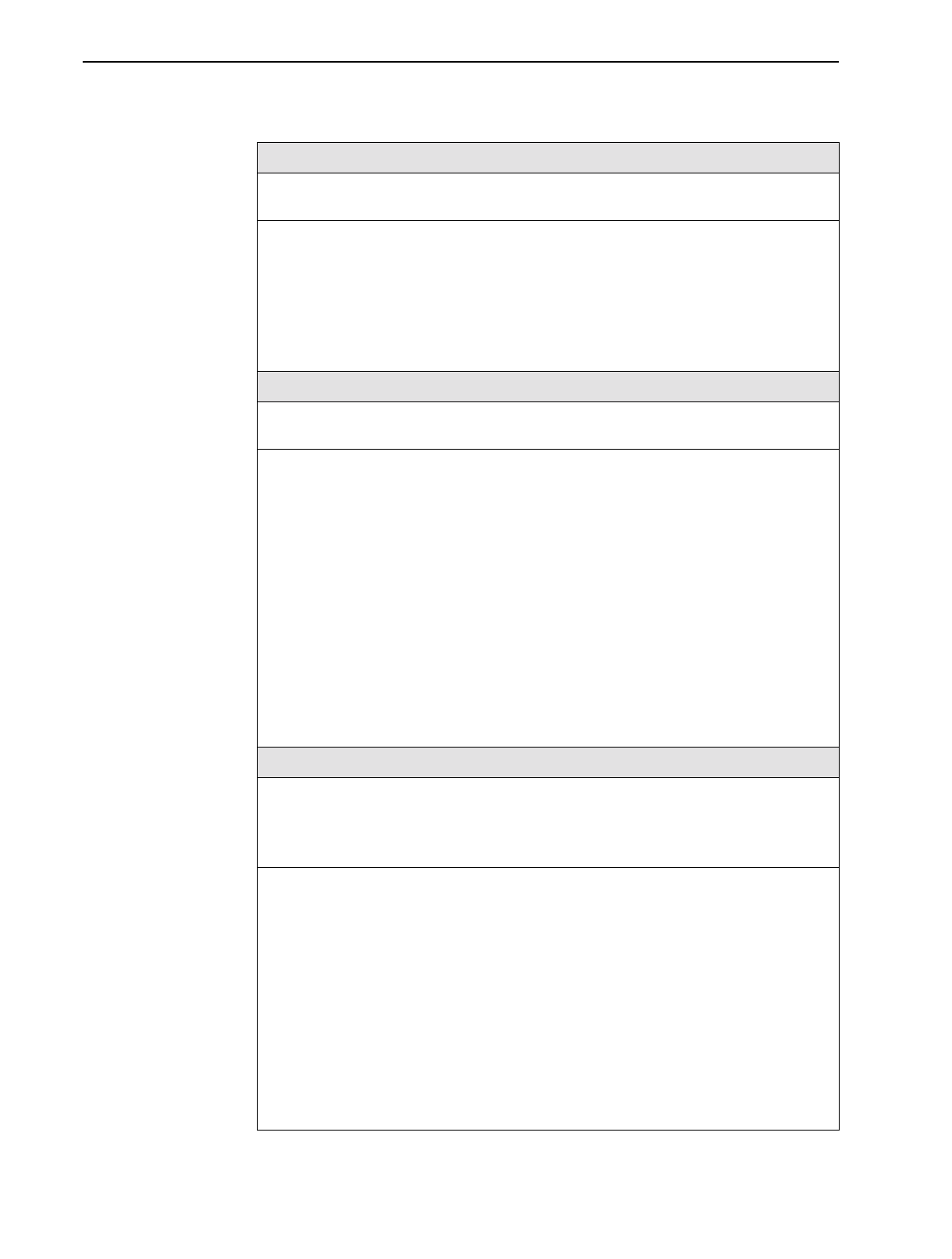
Outbound Phone Number
Possible Settings: 0 – 9, *, #, space, _, –, (, or )
Default Setting: none
Specifies the primary phone number to call (the ISDN Called Party Identifier) for the Link
Profile. Up to 18 valid characters can be entered. Each Outbound Phone Number must be
unique. If not, the
Outbound Phone Number is Not Unique
message appears and
you must enter another phone number.
NOTE: For every originating (outbound) phone number entered, an answering
(inbound) phone number must be entered at the far end, and vice versa.
Currently active calls are not effected when this number is changed.
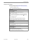
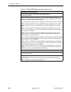
Inbound Calling ID 1 or 2
Possible Settings: 0 – 9
Default Setting: none
Specifies the local phone number of a remote device from which that the unit will accept
calls (the ISDN Calling Party Identifier). Up to 18 digits can be entered. Each Inbound
Calling ID must be unique. If not, the
Inbound Calling ID
n
is Not Unique
message appears and you must enter another phone number.
For remote devices with a PRI DBM, only one Inbound Calling ID is required. Inbound
Calling ID 2 is provided to identify incoming calls from a second phone number assigned
to a remote device with a BRI DBM.
NOTES:
– Inbound Calling ID 2 is only useful when multiple local phone numbers are
programmed at the originating site (e.g., a 2B+D BRI location).
– For every originating (outbound) phone number entered, an answering (inbound)
phone number must be entered at the far end, and vice versa.
Currently active calls are not effected when this number is changed.
0 – 9 – Specifies the numbers in the remote device’s local phone number.
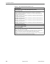
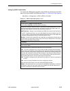
Maximum Link Rate (Kbps)
Possible Settings:
For a BRI DBM:
64, 128
For a PRI DBM:
64 – 1472
Default Setting: 64
Specifies the maximum rate that will be attempted for the frame relay link when it is
activated. The actual rate achieved on the link depends upon the number of successful
calls placed or answered, and the negotiated rate on each call.
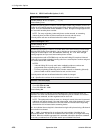
NOTE: This option takes effect as soon as a change is saved. If the rate is increased,
additional calls will be placed. If the rate is decreased, calls will be dropped. For extra
calls to be successful, the Maximum Link Rate must be increased at the originating
device before it is increased at the answering device.
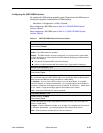
64 – An individual frame relay link is formed and a single call is placed using a B-channel
when the link is activated.
128 . . . 1472 – A constituent link is configured for each multiple of 64 Kbps in the
specified bandwidth. This bundle of constituent links will function as a single frame relay
multilink. When the multilink aggregate link is activated, calls will be placed or answered
on as many constituent links as possible based upon available B-channels.
Table 4-11. ISDN Link Profile Options (2 of 3)


