


C1528M-F (6/05) 11
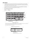
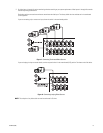
Alarm Inputs
Eight internal alarm inputs are provided on the rear panel of the matrix switcher/controller. These internal alarm inputs are programmable to
associate any camera to any input. A 96 x 16 system provides 16 internal alarm inputs (eight on each CM6800E-48X8 unit).
Up to four ALM2064 Alarm Interface Units can be connected to the CM6800E (main unit only in a 96 x 16 system). Each alarm interface unit can
handle up to 64 alarms.
Auxiliary Outputs
Three internal auxiliary outputs are provided on the back of the CM6800E. Two are relay outputs, and one is an open collector (TTL) output. A
96 x 16 system provides a total of 6 internal relay outputs (three on each CM6800E-48X8 unit). Auxiliary outputs are activated at the keyboard
(except KBD100).
You can also connect up to four REL2064 Relay Interface Units to the CM6800E (main unit only in a 96 x 16 system).
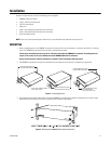
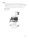
Power, Mounting Methods
The CM6800E operates on 120 V or 230 V, 50/60 Hz. The case mounts in three rack units (5.25 inches or 13.34 cm) of vertical space in a universal
mount, such as a 19-inch (48.26 cm) equipment bay, or to a wall or tabletop.
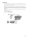
Continuous Operating Device
The CM6800E is a self-contained video surveillance system designed for continuous duty operation. Once installed, no user or service technician
items require the power to be turned off under normal operation. There are two methods for system programming: direct menu control and
indirect control, using a Windows
®
-based setup program supplied by Pelco. Both of these methods are noninvasive and do not require the cycling
of power in order for storage or execution of new software settings. The communication ports use standard low voltage interfaces (RS-232,
RS-422 and RS-485), and all connections and disconnections do not require rebooting or power cycling. Video connections or changes of
termination state do not require rebooting or power cycling.