


14 C1528M-F (6/05)
VIDEO SOURCES
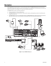
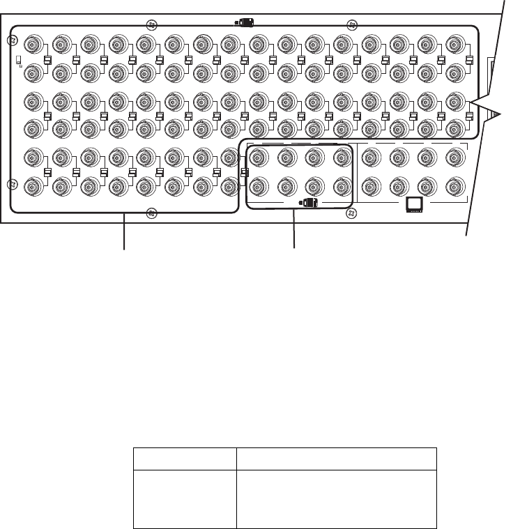
The CM6800E offers 48 full-function video inputs which support Coaxitron PTZ control and video loss detection. Forty video inputs, labeled
1 through 40, can be used for looping video connections with terminating and unterminating switches on the back panel. The eight alternate
source inputs, labeled 41 through 48, are terminated inputs. They do not have loop-through connectors or selectable termination switches, but
otherwise they offer the same functionality as video inputs 1 through 40.
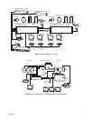
All 48 video inputs also provide the ability to view and interface with other devices, such as Genex multiplexers. If control of the device
connected to the video input is required, connect a data cable between the multiplexer and the CM6800E. Refer to the
Connecting Genex
Multiplexers
section for instructions on connecting and controlling video from a multiplexer.
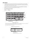
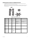
96 x 16 System Default Camera Numbers
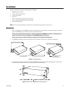
Figure 6.
CM6800E Video Inputs
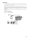
1. Connect video cables at the appropriate video input BNC receptacles on the back of the CM6800E. For best results, use crimp-on BNCs only.
Do not use screw-on BNCs; these typically do not provide adequate ground and signal connections.
Refer to Table A for video coaxial wiring requirements.
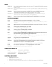
Table A.
Video Coaxial Cable Requirements
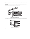
Main unit: Cameras 1-48
Expansion unit: Cameras 49-96
Cable Type* Maximum Distance
RG59/U 750 ft (229 m)
RG6/U 1,000 ft (305 m)
RG11/U 1,500 ft (457 m)
*
Minimum cable requirements:
75 ohms impedance
All-copper center conductor
All-copper braided shield with 95% braid coverage
1
2
3
4
161514131211109
8
765432
1
8765484746
45
40
39
38
37363534
33
3231302928272625
24
232221201918
17
41 42 43
4321
ALT
HZ
7
5
44
40 VIDEO INPUTS SELECTABLE
FOR TERMINATED OR LOOPING
8 TERMINATED ONLY