


C1528M-F (6/05) 19
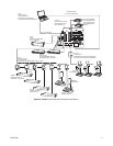
CONNECTING DEVICES THROUGH THE COMMUNICATION PORTS
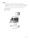
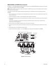
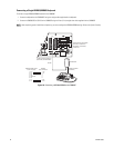
The CM6800E Matrix Switcher/Controller provides eight communication ports on the rear panel for connecting peripheral components.
Instructions are provided in this section for the most commonly used connections.
NOTE:
Connection instructions for other peripheral devices, such as the CM9760-MDA or CM9760-CDU-T, are provided as Pelco Technical Tips.
Connection instructions for compatible products, such as PelcoNet transmission systems and the VMX300 are provided in the appropriate
product installation manual.
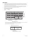
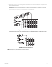
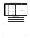
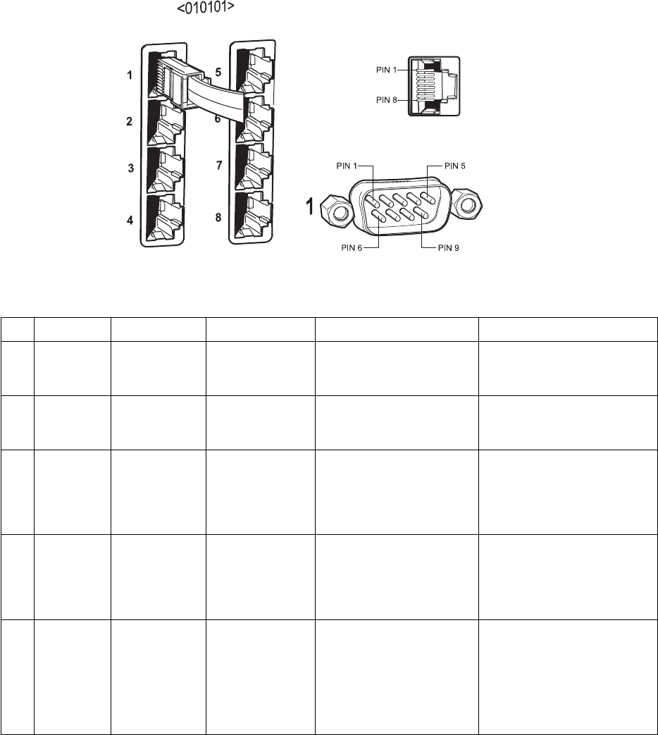
Figure 12.
Communication Port Inputs
Table B.
Communication Port Devices and Wiring
Port Input Type Wiring Pin-Outs Default Device Programmable to Other Device(s)
1 DB9 or RJ-45 RS-232 2 Rx
3Tx
5Ground
PC Setup – CM6800MGR
program
ASCII device
2 RJ-45 RS-232 1 Rx
5Ground
8Tx
CM6800E-48X8 for a
“bay-to-bay” expansion to a
96x16 system
ASCII device (only when used in a
48 x 8 configuration)
3 RJ-45 RS-485 1 Rx+
2 Rx-
5Ground
7 Tx-
8 Tx+
M devices — ALM2064,
REL2064, KBD960
No
4 RJ-45 RS-485 1 Rx+
2 Rx-
5Ground
7 Tx-
8 Tx+
Genex multiplexer CM9760-MDA, ASCII
5 & 6 RJ-45 RS-485 plus power 1 Rx+
2 Rx-
3 KBD power (12V)
4 KBD Ground
5Ground
7 Tx-
8 Tx+
Keyboard (direct powered) –
KBD100, KBD200A, & KBD300A
No
(Continued on next page)