


18 C1528M-F (6/05)
ALARMS
The CM6800E provides numerous alarm handling options. Refer to the
Programming
section for a detailed description.
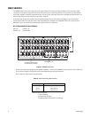
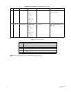
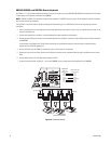
1. Connect wires from the sensors to the respective alarm input points on the connectors at the back of the CM6800E. Each sensor requires
two wires – one wire to the alarm input terminal and a return wire to one of the ground terminals on the connector. The CM6800E supports
eight internal alarms.
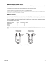
Alarm sensors can be either N.O. (normally open) or N.C. (normally closed) contacts. The CM6800E is set to N.O. as a factory default.
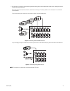
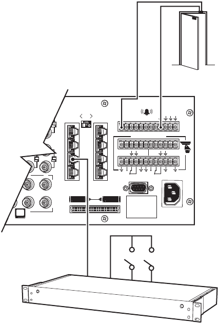
2. If your system requires more than eight alarms, connect an ALM2064 unit to the system. Refer to the
M Devices
section.
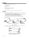
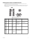
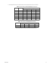
96 x 16 System Alarm Capacity
Figure 11.
Connecting Alarms
Main unit: Alarms 1-8
Expansion unit: Alarms 9-16
1
2
3
4
5
6
7
8
16
876
32
31
432
120/230~
50/60 HZ
25 WATTS
12345678
CONTROL
AT
+
T
-
R
+
R
-
T
+
T
-
R
+
R
-
B
1
2
F
3
1
010101
ALARM
CONTACT
CM6800E-48X8
ALM2064