


C1528M-F (6/05) 51
CAMERA PROGRAMMING
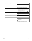
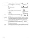
Extended Coaxitron protocol receivers can be operated without any programming changes, other than changing the camera title, if necessary.
For other receiver control protocols, you must select the control type for the device connected to each video input.
If necessary, first program logical camera number.
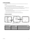
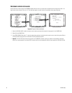
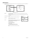
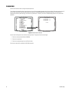
PROGRAM LOGICAL NUMBERS
Default logical numbers start at 0001 and continue sequentially to 0048 (or to 0096 in a 96 x 16 system). To use a different numbering scheme,
program new numbers on the Logical Camera Number screen.
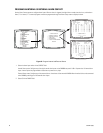
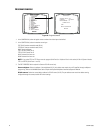
Figure 39. Program Logical Camera Numbers
The numbers in the PHY columns are the physical input numbers; each represents an actual BNC input on the rear panel of the CM6800 and
cannot be changed.
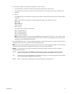
In the LOG field for each physical camera input, assign a valid logical number (0001-9998). A valid number is any number from 0001 to 9998 that
has not already been assigned to a physical camera input.
NOTE: If you change a logical number, you cannot control the camera until you select the new logical number from the keyboard.
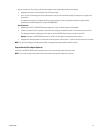
PELCO SWITCHER
MODEL CM6800E
MAIN MENU
1
2
3
4
5
6
7
8
9
10
11
12
13
14
15
CAMERA
LOGICAL CAMERA
MONITOR
ACCESS
TIME & DATE
PORT
PRIORITY
SEQUENCE
MACRO
ALARM CONTACTS
EVENT TIMER
SET AUXILIARY
SET PASSWORD
SYSTEM
ABOUT CM6800E
ENGLISH
RETURN
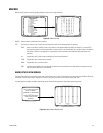
LOGICAL CAMERA NUMBER MENU
PHY LOG PHY LOG PHY LOG
01 0001 17 0402 33 0033
02 0002 18 0403 34 0034
03 0003 19 0404 35 0035
04 0004 20 0405 36 0036
05 0005 21 0500 37 0037
06 0006 22 0501 38 0038
07 0007 23 0502 39 0039
08 0008 24 0503 40 0040
09 0009 25 0504 41 0041
10 0201 26 0505 42 0042
11 0202 27 0601 43 0043
12 0203 28 0602 44 0044
13 0301 29 0603 45 0045
14 0302 30 0604 46 0046
15 0303 31 0605 47 0047
16 0401 32 0032 48 0048
RETURN