


82 C1528M-F (6/05)
Satellite Alarms (Optional)
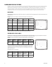
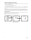
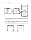
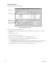
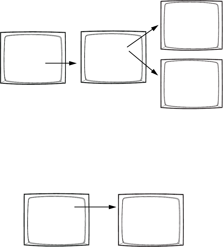
1. Enable the appropriate internal and external alarm contacts. Refer to the Alarm Contacts section for detailed instructions.
Figure 56. Enable Alarm Contacts
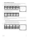
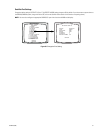
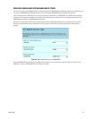
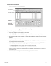
2. In the appropriate Logical Alarm Number screen, assign a logical number for each alarm contact, in sequential order. The logical numbers
assigned in this screen are reported to the CM9740/CM9760 system and they must match the physical numbers configured in the CM9740/
CM9760 system (refer to Program the Alarms File in the CM9740/CM9760 System Settings section). These numbers are used by the
CM9760-KBD keyboard to arm or acknowledge an alarm.
Figure 57. Assign Satellite Logical Alarm Numbers
3. Configure a CM9760-MGR Alarms file for each satellite alarm. Refer to CM9740/CM9760 System Settings in this section.
LOGICAL ALARM NUMBER CONSIDERATIONS:
• If you set the CM6800E to report any CM6800E alarms to the CM9740/CM9760 system, you must assign each CM6800E alarm a logical
alarm number that is unique within the CM9740/CM9760 system (i.e. when used as a satellite device, the CM6800E shares the same pool
of logical alarms numbers as the CM9740/CM9760 system).
•To configure a CM6800E alarm(s) to report only within the CM6800E system, and not to the CM9740/CM9760 system, assign the alarm(s) a
logical alarm number of 0. When the alarm(s) is triggered, the physical number of the alarm(s) appears on the CM6800E system monitor(s).
PELCO SWITCHER
MODEL CM6800E
MAIN MENU
1
2
3
4
5
6
7
8
9
10
11
12
13
14
15
CAMERA
LOGICAL CAMERA
MONITOR
ACCESS
TIME & DATE
PORT
PRIORITY
SEQUENCE
MACRO
ALARM CONTACTS
EVENT TIMER
SET AUXILIARY
SET PASSWORD
SYSTEM
ABOUT CM6800E
ENGLISH
RETURN
ALARM CONTACTS
1 INTERNAL CONTACT
2 EXTERNAL CONTACT
3 VIDEO LOSS
4 ALARM GROUP
5 LOGICAL ALARM NUMBER
RETURN
INTERNAL
ALARM MENU
CONTACT: 1 ENABLE: OFF
ACK TYPE: MANUAL TIME OUT: 10
TYPE: NO PRIORITY: 0
STP CAM DWL CMD ## AUX ##
1 0001 01 PRES 13
– – – –
000
2 0001 00
– – – –
00
– – – –
000
3 0001 00
– – – –
00
– – – –
000
4 0001 00
– – – –
00
– – – –
000
5 0001 00
– – – –
00
– – – –
000
6 0001 00
– – – –
00
– – – –
000
7 0001 00
– – – –
00
– – – –
000
8 0001 00
– – – –
00
– – – –
000
GROUP ENABLE
A B C D E F G H
Y N N N N N N N
RETURN
EXTERNAL ALARM MENU
CONTACT: 001 ENABLE: OFF
ACK TYPE: MANUAL TIME OUT: 10
PRIORITY: 0
STP CAM DWL CMD ## AUX ##
1 0001 00
– – – –
00
– – – –
000
2 0001 00
– – – –
00
– – – –
000
3 0001 00
– – – –
00
– – – –
000
4 0001 00
– – – –
00
– – – –
000
5 0001 00
– – – –
00
– – – –
000
6 0001 00
– – – –
00
– – – –
000
7 0001 00
– – – –
00
– – – –
000
8 0001 00
– – – –
00
– – – –
000
GROUP ENABLE
A B C D E F G H
N N N N N N N N
RETURN
LOGICAL ALARM NUMBER MENU
1 LOGICAL INTERNAL ALARM
2 LOGICAL EXTERNAL ALARM
3 LOGICAL VIDEO LOSS
RETURN
LOGICAL INTERNAL ALARM
PHY
1
2
3
4
5
6
7
8
LOG
0001
0002
0003
0004
0005
0006
0007
0008
RETURN