


C1528M-F (6/05) 27
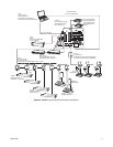
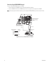
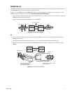
Connecting a Single ALM2064 Alarm Interface Unit
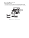
To connect a single ALM2064 Alarm Interface Unit:
1. Connect the ALM2064 OUT port to COM 3 on the CM6800E using the 6-foot (1.8 m) straight data cable supplied with the CM6800E.
2. Set SW2, DIP switches 1-8 to the appropriate positions for the local address (default address setting is 1). Refer to the ALM2064 Alarm
Interface Unit Installation/Operation Manual for instructions.
Figure 19. Connecting a Single ALM2064 Alarm Interface Unit
1
2
3
4
5
6
7
8
16
876
32
31
432
120/230~
50/60 HZ
25 WATTS
12345678
CONTROL
AT
+
T
-
R
+
R
-
T
+
T
-
R
+
R
-
B
1
2
F
3
1
010101
CM6800E-48X8 COM 3
DEFAULT SETTINGS:
M, RS-485, 19200 BAUD,
NO PARITY, 8 DATA BITS,
1 STOP BIT
STRAIGHT CABLE
(SUPPLIED)
RS-485
ALM2064
CONNECT THROUGH
THE "OUT"PORT
ALM2064
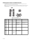
RJ-45 PIN-OUTS
CM6800 COM 3
RJ-45 PIN-OUTS
CM6800 COM 3
RJ-45 PIN-OUTS
1 Rx+
2 Rx-
3 NC
4 NC
5 GROUND
6 NC
7 Tx-
8 Tx+
1 Tx+
2 Tx-
3
4
5
6
7 Rx-
8 Rx+