


C1528M-F (6/05) 59
PORTS (SERIAL/COM PORTS)
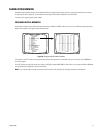
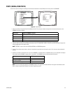
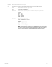
Use the Port screen to configure the settings for each device connected to a Serial/COM port on the rear panel of the CM6800E.
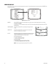
Figure 46. Port Screen
1. Select the number of the desired Serial Port/COM port (01-10). The serial port numbers correspond to the communication ports on the
CM6800E rear panel as follows:
2. Select the device connected to the COM port; the values in the TYPE, BAUD RATE, PARITY, DATA BITS, and STOP BITS fields change to the
settings appropriate for the specific device.
NOTE: “KBD300” is used to refer to the KBD100, KBD200A, and KBD300A keyboards.
3. Optional: Some device options allow a choice of communication type, baud rate, and/or parity rate. If this is the case, select the desired
settings.
4. Optional: If you select an ASCII device or if you use the CM6800E as a satellite device in a CM9760 system, you can select ON in the Report
Alarm field to set the CM6800E to report alarms to that device. The CM6800E reports the following alarm information:
NOTE: The alarm number (#) reported by the CM6800 is based on the logical alarm number defined in the Logical Alarm Number screen.
Refer to Assign a Logical Alarm Number in the Alarm Programming section.
Serial Port Input on CM6800E rear panel
01 COM 1 (accessed through either the DB9 input or RJ-45 port)
02-08 COM 2-8 RJ-45 inputs
09 PTZ-A control input
10 PTZ-B control input
Action ASCII text
An alarm is triggered #Ea
An alarm is cleared #Ia
An alarm is acknowledged #Ka
PELCO SWITCHER
MODEL CM6800E
MAIN MENU
1
2
3
4
5
6
7
8
9
10
11
12
13
14
15
CAMERA
LOGICAL CAMERA
MONITOR
ACCESS
TIME & DATE
PORT
PRIORITY
SEQUENCE
MACRO
ALARM CONTACTS
EVENT TIMER
SET AUXILIARY
SET PASSWORD
SYSTEM
ABOUT CM6800E
ENGLISH
RETURN
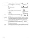
SET SERIAL PORT 05
DEVICE:
TYPE:
BAUD RATE:
PARITY:
DATA BITS:
STOP BITS:
REPORT ALARMS:
KBD300
RS485
9600
ODD
8
1
- - -
RETURN