


10 C578M-A (4/05)
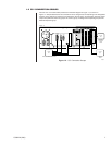
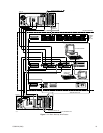
In addition to communications, there are number of additional functions handled by the CM9760-CCC.
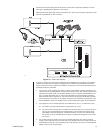
POWER The power-input connector, fuse, and ON/OFF switch are located here. Input
power for the entire HS originates here. Power is distributed to the CPS and SEU
subunits via DB37 common bus connections.
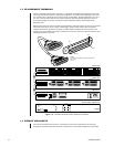
LOGGING
PRINTER PORT This is used, if desired, as an output logging device for system or status reports
related to hot switch operation only. The port supports dot matrix printers capable
of IBM or Epson emulation modes, such as the Okidata 320 (non-turbo) and the
Okidata 390 (turbo) or 391 (turbo).
LEDs The FAULT, A, and B LEDs are located on the front panel of the unit. These give
visual indications of system status with respect to control, mode of operation, and
system failure. See the
LEDs
section of
3.3 Operator Tools.
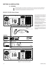
FRONT PANEL
BUTTONS The front panel buttons are utilized by the operator for responding to system
errors, for checking system status, and for operational control when changes are
made to system hardware and/or software. See the
Front Panel Buttons
section
of
3.3 Operator Tools
.
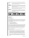
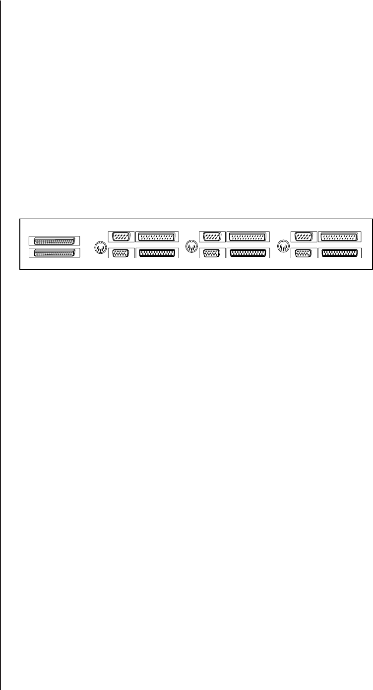
THE CPS (Computer Peripheral Switch)
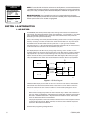
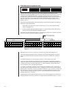
The connectors on the rear of the CPS are divided into three duplicate sections. Each section contains
an AT KBD connector,
a VGA connector,
a PRINTER connector,
a COM 1 connector (port), and
a COM 2 connector (port).
Each duplicate section is labeled. From left to right, they are the CC1 ‘A’ section, the CC1 ‘B’ section,
and the EQUIPMENT section. The first two (CC1 ‘A’ and CC1 ‘B’) are connection input destinations
for the corresponding switch it interfaces—one from the A-side, and one from the B-side switch. The
third section (EQUIPMENT) provides the connectors to which the following standard diagnostic
devices can be attached:
1. An AT keyboard (to the AT KBD connector)
2. A VGA monitor (to the VGA connector)
3. A system printer (to the PRINTER connector)
4. A PC W/Pelco MGR software (to the COM 1 port)
As a user, you are always connected (through either one matrix switch or the other) to the diagnostic
tools that are attached to the EQUIPMENT output ports. The switch through which you operate (the
one in control and designated the Master) is normally granted automatic access to those devices
(default). If control is switched, the backup switch (Slave) becomes the designated Master, roles are
reversed, and the output diagnostic connections change to follow suit. This happens automatically if
DIP switch 1-2 is ON and DIP 1-6 is OFF (default). See Figure 2-4, DIP Switch Configuration.
Note that only four diagnostic devices are listed for the five available output ports. Two of the five
output ports deserve further comment.
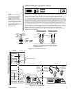
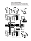
COM 1 is reserved for the connection of the PC with MGR software (see Figure 1-11).
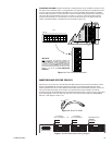
COM 2 can be used in two ways:
1. As a “user” defined configuration for the connection of devices and/or electronic equipment to
the COM 2 A and B inputs and to the COM 2 EQUIPMENT output port. The COM 2 ports are
D-type, 25-pin connectors, and can be used for the connection of user-optioned equipment.
Applied voltages to COM 2 connector pins should not exceed 25 VDC. For this use, the
operation of the COM 2 port is not necessary for the successful operation of any function of the
HS. Insert A of Figure 1-6 is a diagrammatic drawing of the wiring of the COM 2 connectors.
2. For the connection (to the EQUIPMENT section’s COM 2 output port) of an RS-232, DT (Data
Translator). As part of the CPS package, three DB25 (female) to DB9 (male) adapters are pro-
vided for this purpose (along with the associated cabling for the A- and B-side inputs to these
adapters).
AT
KBD
AT
KBD
AT
KBD
CC1 A CC1 B EQUIPMENT
OUT
IN
COM 1 COM 2
VGA PRINTER
COM 1 COM 2
VGA PRINTER
COM 1 COM 2
VGA PRINTER
20055