C578M-A (4/05) 29
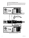
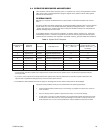
SYSTEM UPDATE PROCEDURE
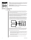
Table E (see NOTE at end of Table) describes the procedure to follow when it is necessary to update,
change, or add any hardware/software item associated with a hot-switched, online system node. The
procedure, explicitly detailed in Table E, proceeds through the following steps:
1. Manually puts A- or B-side into asynchronous mode (Table E starts with A-side), and takes the
opposite side offline.
2. Repairs or updates to components of the offline system are made.
3. Power is applied to the offline unit, it is then synchronized, after which asynchronous mode is
asserted on the same side.
4. The opposite side is taken offline where the same updates and changes are made, the unit is
powered up, and then the system is resynchronized.
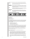
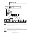
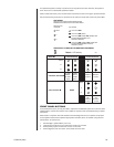
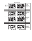
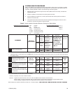
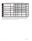
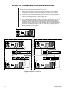
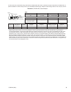
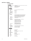
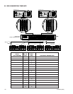
Table E. System Update of Hardware/Software, Starting from Default Mode
Abbreviations and References Used Mstr = Master Front Panel SELECT Buttons CC1 A
Slv = Slave CC1 B
Sync = Synchronous KVD A
Async = Asynchronous KVD B
S mode = Synchronous mode
A mode = Asynchronous mode
FP = Front Panel
SIDE
A-side
B-side
A
B
A
B
A
B
A
B
STATUS
Mstr/Slv
Master/
Slave
Mstr/Slv
Master/
Slave
Mstr
Slv
Mstr
Mstr
Mstr
MODE
MODE =
Async/Sync
Asynchronous/
Synchronous;
else Offline
MODE =
Async/Sync
Asynchronous/
Synchronous;
else Offline
Sync
Sync
Async
Online
Async
Online
Async
Offline
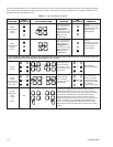
LEDs (A/B)
LEDs A and B alter-
nate in S mode. LED
for primary is On
long, Off short; LED
for secondary is
Off long and On
short. In A mode, the
con-trolling units LED
is ON solid.
A On long
B On short
A On solid
B Off
A On solid
B Off
A On solid
B Off
COMMENTS
FP Button
(User Action)
CC1 A
[2 beeps]
KVD B
FAULT LED
FAULT
On or Off
FAULT
Off
FAULT
Off
FAULT
Off
FAULT
Off
1 Default Operating Mode
Press and hold CC1 A for two
beeps (forces A side to Async
mode; B-side is still online, but not
synched.
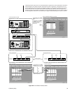
Press KVD B, so that diagnostic tools
are available for the B-side update,
which will be done first (equipment
and/or software).
A “Ctrl + Q” keypad operation on B-
side takes it offline. The diagnostic
screen should show the DOS prompt
on the B-side.
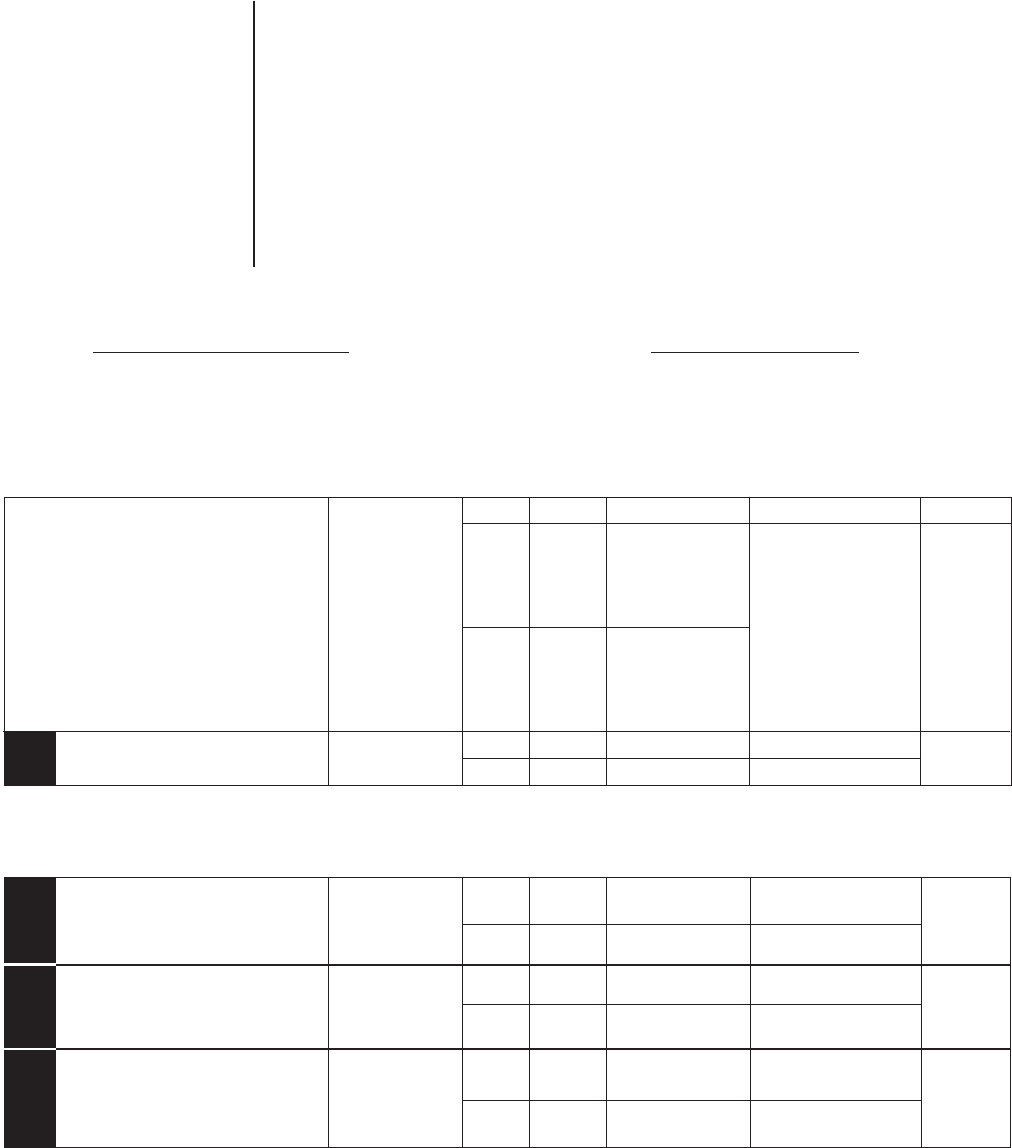
2
3
4
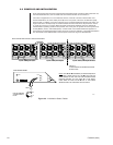
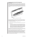
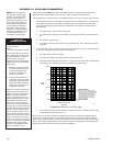
• If you are in B-side Master, Synchronous Mode, switch to A-side Master, synchronous mode (as above) to follow the procedure presented.
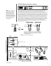
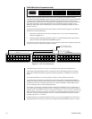
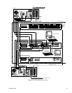
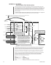
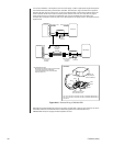
• Place DIP switch 1-2 (see Figure 2-4) to the Off position so that all CPS diagnostic tools (VGA monitor, etc.) are under user control during
the update process.
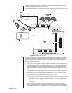
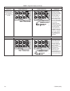
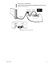
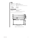
With the B-side offline, you can do any or all of the following:
Hardware: Physically move, add, or delete hardware.
Software: Upgrade the system software on the CC1 and/or the MGR software located on the external PC.
Amend, update, or replace configuration files to correspond to the new equipment configuration using the MGR program.
Transfer updated configuration files to the appropriate hard-drive directory on the B-side CC1.
When changes are complete, initialize the B-side CC1 to “Setup Complete.” THE B-SIDE WILL NOW BE ONLINE, BUT NOT SYNCHED.