


C578M-A (4/05) 3
LIST OF ILLUSTRATIONS
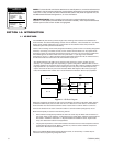
SECTION 1.0: INTRODUCTION
1-1. HS Block Diagram................................................................................................................6
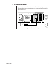
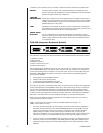
1-2. CC1 Connection Groups ......................................................................................................7
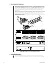
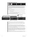
1-3. HS Rear Views and CCC Subunit Front Panel ....................................................................8
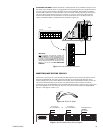
1-4. Data Cable Identification ......................................................................................................9
1-5. Data Cable Wiring ................................................................................................................9
1-6. COM 2 Port Options............................................................................................................ 11
1-7. SEU Port Relationships ......................................................................................................12
1-8. Port Connection Mnemonic.................................................................................................13
1-9. RJ-45 Pin Detail ..................................................................................................................13
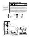
1-10. SEU Master/Slave Wiring Diagram .....................................................................................13
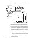
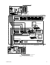
1-11. Basic Hookup, Wire Routes ................................................................................................15
SECTION 2.0: INSTALLATION
2-1. Data Cable Wiring Detail
2-2. Diagnostic Group, Cabling Detail .........................................................................................17
2-3. External Expansion Cabling Detail.......................................................................................18
2-4. DIP Switch Configuration .....................................................................................................19
2-5. Initialization Status, Default..................................................................................................20
SECTION 3.0: OPERATION
3-1. System Window Online Status.............................................................................................26
SECTION 4.0: APPENDICES
A4-1. Hot Switch Comparison Summary.....................................................................................32
A4-2. HS-NIU Connections .........................................................................................................34
A4-3. Hot Switch Interfaced NIU .................................................................................................. 35
A4-4. Data Rate vs. Cable Length...............................................................................................36
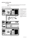
A4-5. Keyboard (Local Hookup) ..................................................................................................37
A4-6. Remote Wiring a CM9760-KBD .........................................................................................38
SECTION 5.0: GENERAL
5-1. CM9760-HS Dimension Drawing .........................................................................................41
LIST OF TABLES
SECTION 3.0: OPERATION
A LED Activity ...............................................................................................................................23
B Front Panel Button Operation ...................................................................................................24
C System FAULT Response.........................................................................................................25
D Diagnostic Displays ..................................................................................................................27
E System Update of Hardware/Software, Starting from Default Mode ........................................29
SECTION 4.0: APPENDICES
Table A4-A. (TIA/EIA-422*) Cable Example ..................................................................................39