


18 C578M-A (4/05)
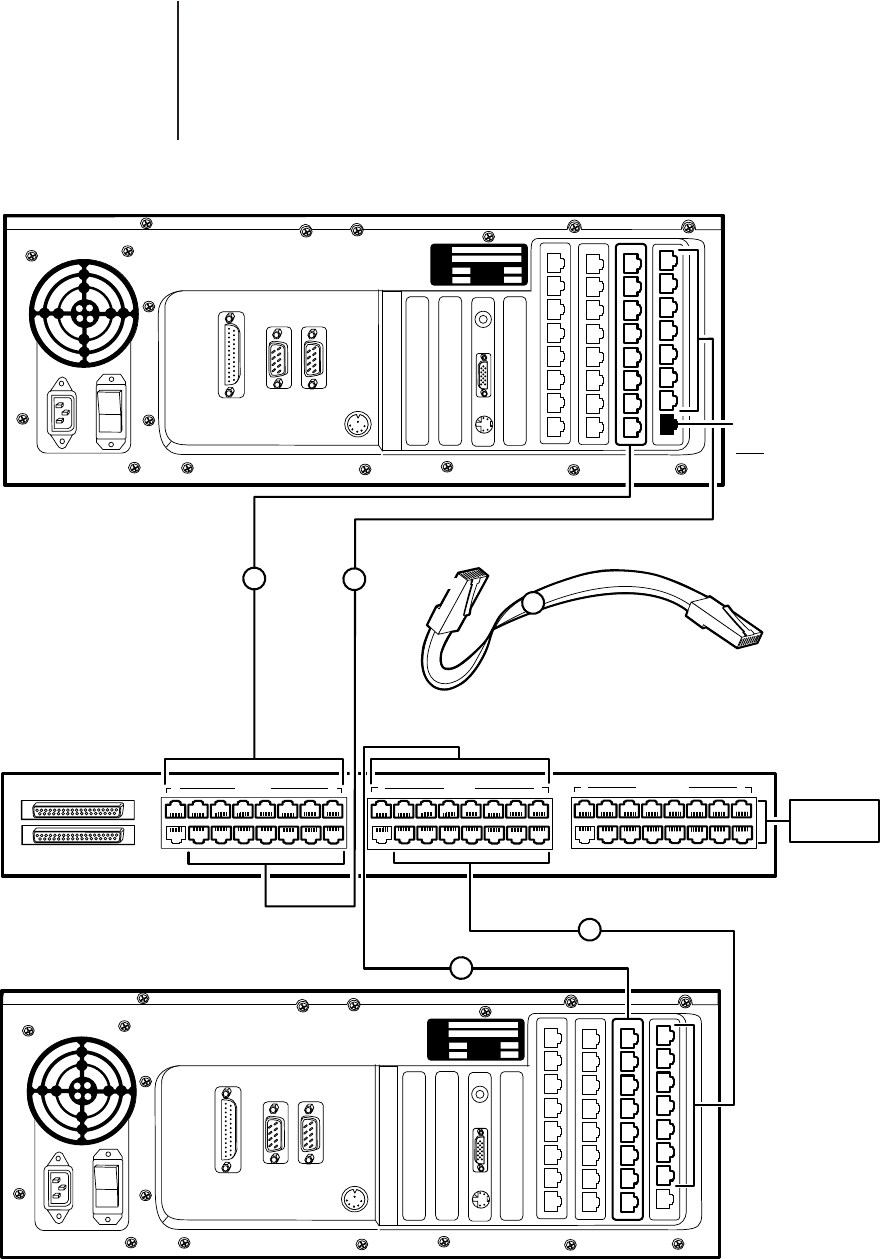
9700-CC1 TO SEU (Expansion Group)
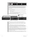
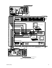
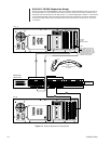
Devices connected to the EQUIPMENT output port (which the designated Master switch has access to)
are implemented here. Port destinations for cable connection inputs from the matrix switches are not
predefined. This was discussed in the
SEU
portion of
1.4 Subunit Highlights
in
Section 1.0 Introduction
.
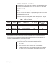
It is recommended that the SEU connection template (located at the back of the manual) be utilized here.
All interconnecting cables are RJ-45, M-M, RS-422, and are provided for the input (CC1 ‘A’ and ‘B’)
connections.
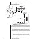
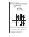
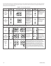
Figure 2-3. External Expansion Cabling Detail
1 CC1 A 8 1 CC1 B 8 1 EQUIPMENT 8
CC1 A
MODEL
SERIAL
VOLTS WATTS
FREQ AMPS
PRINTER
COM 1 COM 2
MODEL
SERIAL
VOLTS WATTS
FREQ AMPS
RJ-45/M-M
CC1-SEU
SERCOM-SERCOM
CM9760-SEU
(REAR VIEW)
DEVICES:
MXBs, KBDs,
RECEIVERS, ETC.
CC1 B
PIN 8
CROSSOVER
OR
REVERSE CABLE (SUPPLIED)
3 FT (0.9 M)
1
1
PRINTER
COM 1 COM 2
1
PIN 1
1
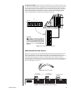
OUT
IN
9
16
1
PORT 5
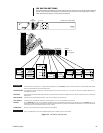
NOTE: SERCOM PORT FIVE ON
EACH RESPECTIVE SWITCH IS
RESERVED FOR THE DATA LINE
CONNECTION BETWEEN IT AND
THE APPROPRIATE RJ-45 ON THE
CM9760-CCC UNLESS RS-232
COMMUNICATION IS USED.
20067