C578M-A (4/05) 25
3.4 OPERATOR RESPONSES AND METHODS
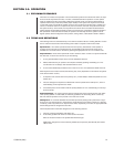
User interaction with the HS is necessary when (1) a system error occurs, which generates a FAULT
LED, and (2) when a software/hardware change or upgrade to the system must be made. System
FAULTS are discussed first.
SYSTEM FAULTS
Although error response is addressed in the previous table, not all FAULT situations are covered
there.
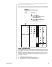
Any alarm results in the FAULT LED being lit. An associated audible notification also occurs if optioned
via DIP switch. You can turn off audible notification (default) by setting DIP switch 1-1 to the OFF
position (see Figure 2-4). Note that this does not affect the audible two-beep tone associated with
manually asserting asynchronous mode.
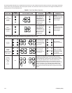
In any FAULT situation, system control is passed to or remains with the “working” CC1, which then
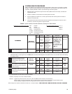
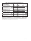
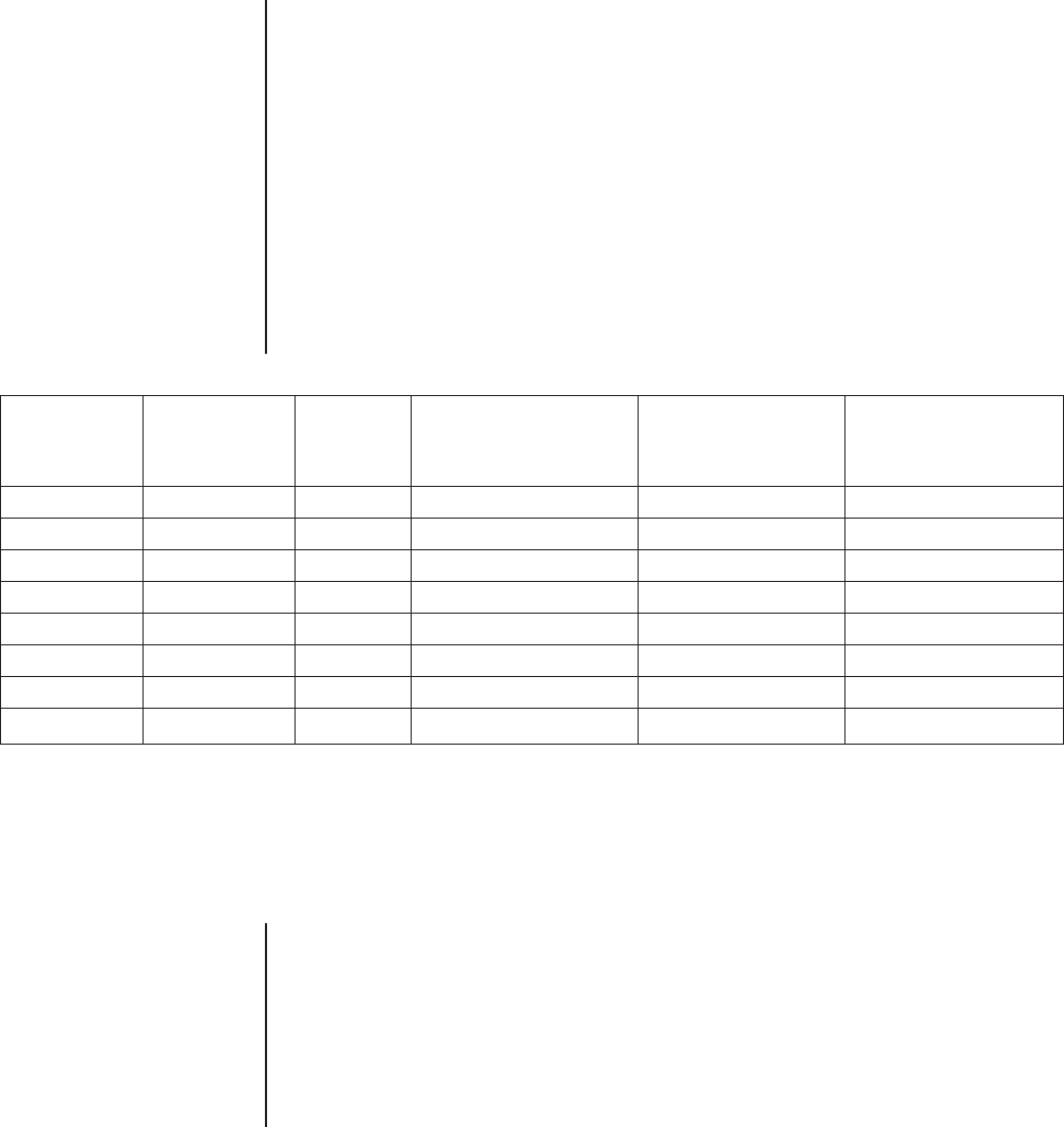
automatically reverts to or remains in asynchronous mode. The following table summarizes system
operation and the necessary user response to any FAULT variation, given the stated initial conditions:
Table C. System FAULT Response
IF THE TO ACK the FAULT LED
CONTROLLING AND THE The FAULT LED is Lit and (and the audible, if ON),
SIDE IS: MODE IS: AND SIDE THE RESULT IS: the ___ LED is On PRESS & HOLD CC1 __for
two beeps:
A Synchronous A Fails B goes to Asynchronous B B
A Synchronous B Fails A goes to Asynchronous*** A A
A Asynchronous* A Fails B goes to Asynchronous** B B
A Asynchronous B Fails A remains in Asynchronous N/A N/A
B Synchronous B Fails A goes to Asynchronous A A
B Synchronous A Fails B goes to Asynchronous*** B B
B Asynchronous A Fails B remains in Asynchronous N/A N/A
B Asynchronous* B Fails A goes to Asynchronous** A A
* In this instance, the side in question is in asynchronous mode as the result of operator action, not because the opposite side had
previously failed.
** If you are in A or B, asynchronous mode because the opposite side previously failed and now the side in question fails before the
opposite side is repaired and brought back up, then the entire system is down.
*** The “RESULT” mode indicated here will not appear on the diagnostic monitor until the FAULT LED is acknowledged.
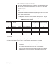
The above cases of FAULT activity can be summarized in the following statements:
• If both interfaced matrix switches (CC1s) are working, any system error leaves one of the two
CC1s in control.
• Any error always puts the system in asynchronous mode, if it is not there already.
• In each case, to turn OFF or ACK the FAULT, you must manually reassert asynchronous mode
for the side in control after the error occurs (the LED light for the side in control [A or B] is ON
solid). Hold the CC1 A or CC1 B front panel button until the audible two-beep tone is heard.


