


12 C578M-A (4/05)
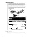
THE SEU (Serial Expansion Unit)
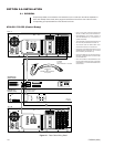
The SEU subunit of the HS, like that of the CPS, is also divided into three sections. Devices
connected to the SEU EQUIPMENT output ports are under the control of only one CC1 at a time. The
controlling switch is designated the Master, regardless of mode (synchronous or asynchronous).
Unlike the CPS, however, there are no predefined port designations for SEU Sercom input ports that
physically correspond to the port designations as they are defined by physical location on any
9760-CC1 matrix switch. On the matrix switch, port 5 is port 5 and is always located at the “port 5”
position, and so on.
The physical relationship between matrix switch Sercom outputs and the A/B inputs on the SEU are
defined by the following statements:
1. The function of each Sercom input port on the SEU (CC1 ‘A’ or CC1 ‘B’) is characterized by
whatever is plugged into it.
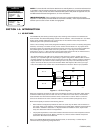
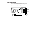
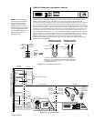
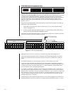
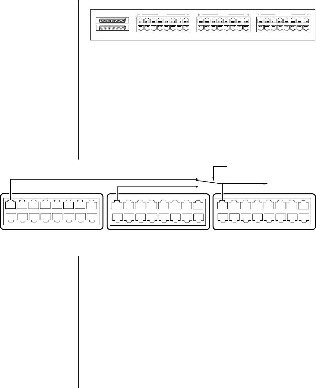
2. A specific physical relationship (depicted in Figure 1-7) exists internally between SEU Sercom
inputs (A or B) and associated SEU EQUIPMENT outputs.
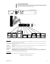
The Sercom ports on the SEU shown in Figure 1-7 are isolated and numbered (for explanatory purposes);
the ports on the SEU are physically related as illustrated.
Figure 1-7. SEU Port Relationships
The depiction above shows CC1 ‘A’ input A1, connected to the output device attached to E1.
The physical relationship depicted above is repeated for all corresponding physical port locations;
that is, A2 is related to B2 and the output E2 in the same way that A1 is related to B1, and the E1
output.
This relationship holds true for the remaining port locations: A3-A16, B3-B16, and E3-E16.
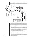
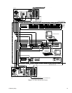
In line with the port relationship just discussed, you must also maintain corresponding equipment
integrity with respect to the input port locations chosen for attaching A- and B-side input cables. This
is so that output control, from either matrix switch, of a device connected to a specific SEU output
port, corresponds, in fact, to the same physical device.
For example: If a matrix bay is hardware-software configured for attachment to port 7 on 9700-CC1 A,
then it also must be configured the same for port 7 on 9700-CC1 B, since the CC1s must be hardware-
software clones of each other. If you then run a cable from 9700-CC1 A, port 7, to the CC1 ‘A’ side of the
SEU and attach it to the A1 port, then you must also run a corresponding cable from 9700-CC1 B, port 7,
to the CC1 ‘B’ side of the SEU and attach it to port B1. The matrix bay itself, is connected to the corre-
sponding output port, E1, on the SEU.
As indicated above, the configured outputs of 9700-CC1 ports can be plugged into any input port on
the appropriate SEU, as long as you allow for the physical constraint illustrated in Figure 1-7, above.
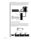
OUT
IN
1 CC1 A 8 1 CC1 B 8 1 EQUIPMENT 8
9
16
20085
RELAY ACTIVATION FOLLOWS
THE CC1 IN CONTROL (MASTER)
CC1 A CC1 B EQUIPMENT
A
B
A1 A2 A3 A4 A5 A6 A7 A8
A9 A19 A11 A12 A13 A14 A15 A16
B1 B2 B3 B4 B5 B6 B7 B8
B9 B19 B11 B12 B13 B14 B15 B16
E1 E2 E3 E4 E5 E6 E7 E8
E9 E19 E11 E12 E13 E14 E15 E16
20062