


8 C578M-A (4/05)
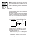
1.4 SUBUNIT HIGHLIGHTS
The main characteristics and functions of each subunit of the HS are discussed in the following
paragraphs. Important points that need to be understood for a successful installation are discussed.
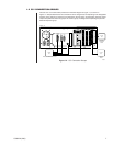
1.3 HS HARDWARE THUMBNAIL
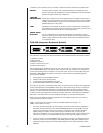
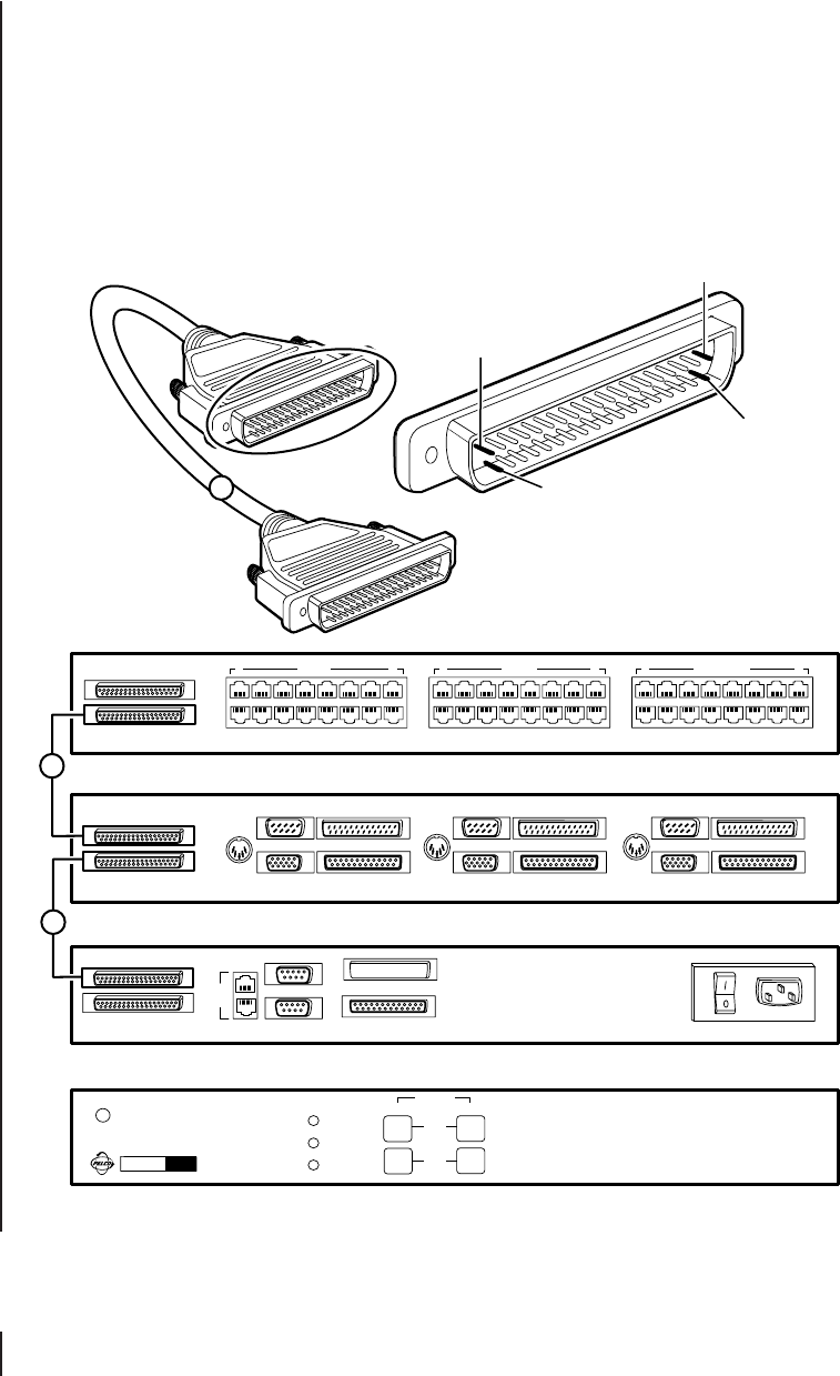
Figure 1-3 expands the HS portion of Figure 1-1 to illustrate an uncluttered, thumbnail rear view of the
hot switch subunits that comprise a default HS configuration. Connection cable destinations from each
CC1 (matrix switch), referenced in the previous figure, are attached to the appropriate side (CC1 ‘A’ or
CC1 ‘B’) of the hot switch subunits. The subunit acronyms have the following meanings: the CCC
(Computer Changeover Control), the CPS (Computer Peripheral Switch) and the SEU (Serial
Expansion Unit).
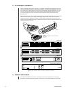
Note that the CCC front panel is included in this illustration. Operation buttons for the user are located
there. Also shown is the 37-pin, D-type, molded cable, used to create common bus connectivity
between the subunits. (Except for the CPS, one DB37 cable is supplied with each subunit). Front
panels for the CPS and SEU are similar to that shown for the CCC (minus the operation buttons), with
labeling appropriate to each unit.
Figure 1-3. HS Rear Views and CCC Subunit Front Panel
SYSTEM
9760
PWR
LOGGING PRNTR
OUT
IN
A
B
SELECT
AB
CC1
KVD
1
1
DB37/M-M
HOT SWITCH INTERCONNECT BUS CABLE (SUPPLIED)
2.5 FT (.76 M)
CCC-SEU
PIN 19
PIN 37
PIN 20
PIN 1
CM9760-SEU
CM9760-CPS
CM9760-CCC
(FRONT PANEL) CM9760-CCC
CM9760-CCC
HOT SWITCH
Made in USA
A
B
FAULT
A
B
AT
KBD
AT
KBD
AT
KBD
COM 1 COM 2
VGA PRINTER
1
CC1 A CC1 B EQUIPMENT
OUT
IN
OUT
IN
120-240 VAC 50/60 Hz
1 CC1 A 8 1 CC1 B 8 1 EQUIPMENT 8
9
16
C
C
1
COM 1 COM 2
VGA PRINTER
COM 1 COM 2
VGA PRINTER
20059