


C578M-A (4/05) 13
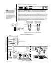
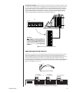
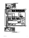
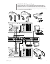
MASTER/SLAVE STATUS FOR CC1
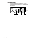
Sercom port 1 on the CC1-A or CC1-B side of the SEU subunit may be wired to provide the current
status of the CM9760-HS. This wiring connection will allow for monitoring that alerts the user to
primary (master) CPU (CC1) failure. When the secondary (slave) CPU assumes primary control, the
user can be alerted remotely via the closure of an external alarm. This connection is made by
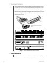
constructing an RJ-45 terminated wire (not provided) and shorting pins 1 and 2 (CC1-A) or pins 7 and
8 (CC1-B) together on the CC1 side
only
. The CC1 port (A or B) is connected to the EQUIPMENT
side port 1. See Figures 1-9 and 1-10.
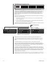
Figure 1-9. RJ-45 Pin Detail
Figure 1-10. SEU Master/Slave Wiring Diagram
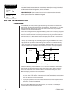
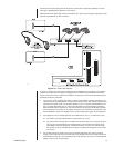
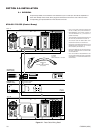
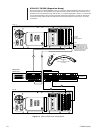
A NOTE OF CAUTION: Random attachment of cabling between CC1s and SEUs can lead to confu-
sion about what is attached where. It is suggested that you map the physical port arrangement found in
your CC1 outputs to those utilized on the SEU (as far as that is possible). One method is to mentally
rotate the SEU (clockwise or counterclockwise, it does not matter) and associate the port locations you
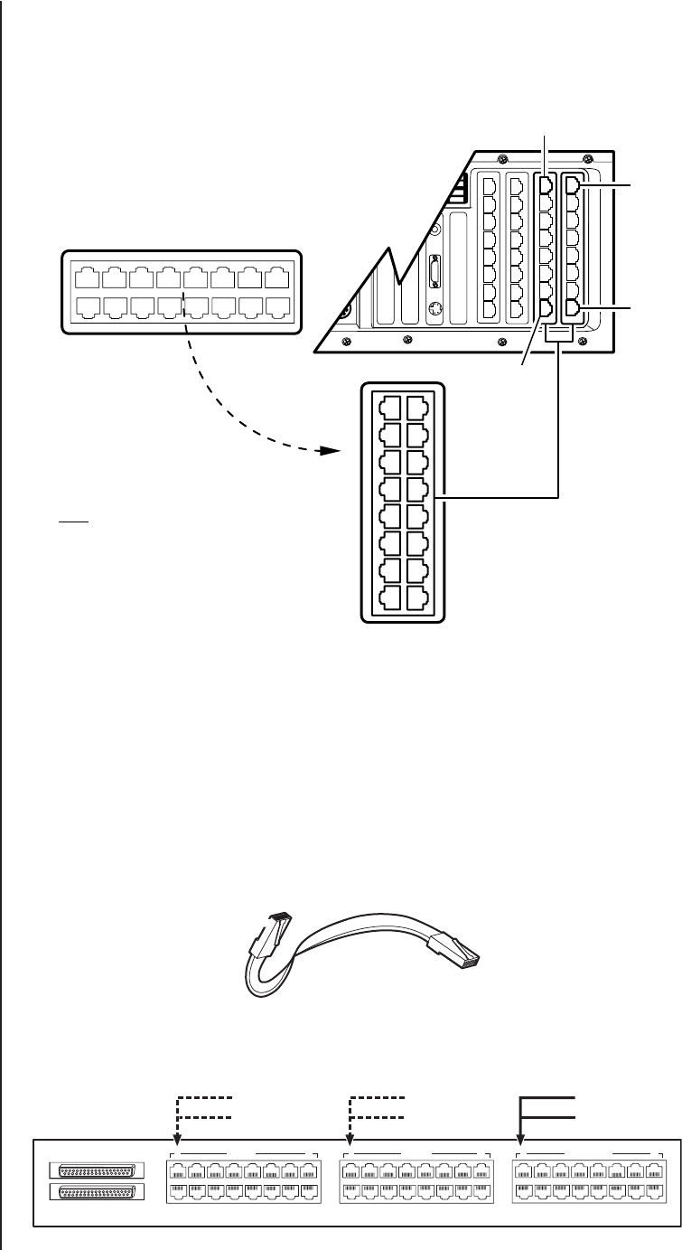
use on the SEU to those existing on the CC1. In Figure 1-8 , the CC1 ‘A’ side of the SEU is shown
rotated counterclockwise. You can extend the use of this visual mnemonic to the SEU’s B side, the
output, and additional SEUs, if needed (also see the NOTE in Figure 1-8).
Figure 1-8. Port Connection Mnemonic
CC1 ‘A’
CC1 ‘A’
CC1 ‘A’
SEU
20
12
5
13
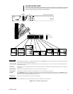
IMPORTANT
NOTE: ALTHOUGH THE METHOD CHOSEN FOR
KEEPING SEU PORT CONNECTIONS STRAIGHT IS,
A
T BEST, ARBITRARY, PELCO RECOMMENDS THAT
IT IS BEST TO FOLLOW A DESIGNATED TEMPLATE
A
S AN AID IN TRACKING SEU PORT CONNECTIONS.
ONE IS PROVIDED FOR YOU AT THE BACK OF THIS
MANUAL. IT IS CALLED THE SEU CONNECTION
TEMPLATE.
OUT
IN
1 CC1 ‘A’ 8 1 CC1 ‘B’ 8 1 EQUIPMENT 8
9
16
MASTER
SLAVE
ALARM OUT
CC1 A PORT #1
(PIN 1 & 2 SHORTED)
CC1 A PORT #1
(PIN 7 & 8 SHORTED)
EQUIPMENT PORT #1
OR
PIN 8
PIN 1