


32 C578M-A (4/05)
APPENDIX 4.2 HS UPDATE
(Previous Model of Hot Switch Installed)
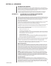
The previous model of the hot switch has existed for some time. Those acquainted with its opera-
tional characteristics know the uses and characteristics of a hot switch. This is an advantage, on one
hand, compared to those not so acquainted. On the other hand, that advantage is somewhat eroded
by the fact that there are some major differences involved in the hookup and use of the new HS.
Ingrained familiarity with the previous model can lead to simple mistakes in installing and operating
the current model.
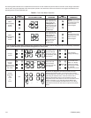
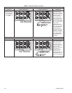
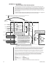
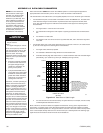
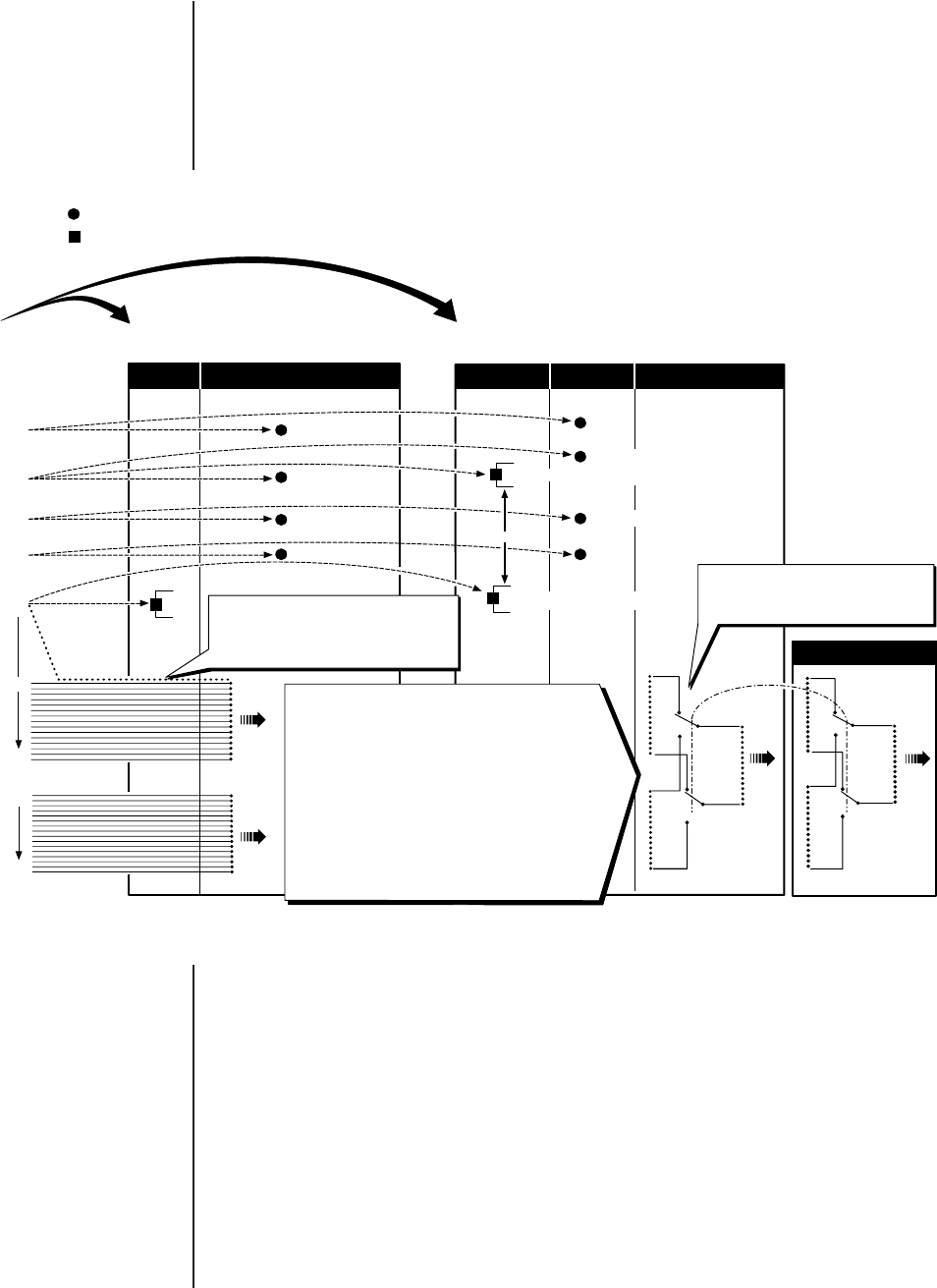
To ease the transition process for those migrating to the current hot switch, Figure A4-1 highlights the
connection similarities and differences between previous and current HS models.
Figure A4-1. Hot Switch Comparison Summary
The intervening connections between CC1 Source and HS Destination outputs in the previous hot
switch were implemented using a combination of specialized cabling and hardwired paths. This
resulted in a more or less fixed relationship between the Source and Destination connections.
The Source and Destination relationships in the current hot switch are defined by the connection
cabling alone. The result is a more flexible hot switch. This flexibility can be seen in Figure A4-1.
Even so, you can set up the Source-Destination relationships of the connectors for the current hot
switch in the exact same manner as was done in the previous hot switch. This relationship
equivalency can between the previous and current hot switch can be read off directly from
Figure A4-1 for the current hot switch as follows:
VGA ----------------------------- VGA
PRINTER ---------------------- PRINTER
RS-422 DATA LINE --------- RS-422 DATA LINE
COM 1-------------------------- COM 1 (PC W/MGR)
COM 2-------------------------- COM 2 (DT or RS-232 ASCII DEVICE CONNECTION).
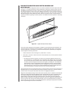
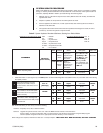
DEPICTS THE PHYSICAL RELATIONSHIP BETWEEN THE A-
AND B-SIDE INPUT PORTS AND SEU OUTPUT PORTS.
THERE IS NO MAPPING CORRESPONDENCE BETWEEN CC1
SERCOM PORT OUTPUTS AND A- OR B-SIDE INPUTS ON
THE SEU. ANY OUTPUT FROM A CC1 A- OR B-SIDE SERCOM
PORT CAN BE PLUGGED INTO ANY AVAILABLE A- OR B-SIDE
INPUT PORT, RESPECTIVELY, ON THE SEU. THE ONLY
CONSTRAINT IS THAT CABLING ON THE A-SIDE INPUT PORT
IS DUPLICATED ON THE B-SIDE AND THE OUTPUT PORT
CONNECTION, WITH RESPECT TO PORT LOCATION
AND THE TYPE OF DEVICE CONNECTED. NOTE THAT
WE GAIN THE USE OF AN ADDITIONAL OUTPUT PORT
COMPARED TO PREVIOUS MODELS SINCE PORT 5 (LIKE
ALL OTHER PORTS) IS NOT HARDWIRED AND THEREFORE
IS NOT LOST TO DATA LINE HOOKUP.
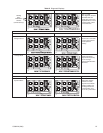
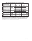
AS SHOWN, THIS DEPICTS A-SIDE CONTROL
OF THE OUTPUT. CONTROL IS DETERMINED
BY SYSTEM CONFIGURATION, SUBJECT TO
OPERATOR INTERVENTION.
ALTHOUGH WIRED TO ITS MIRROR IMAGE
OUTPUT PORT ON THE CCS-PNL, THE PORT
CANNOT BE UTILIZED BY EXTERNAL DEVICES
IF THE SOURCE PORT IS UTILIZED FOR THE
DATA LINE BETWEEN THE CC1 AND THE CCS.
LEGEND: SOURCE WIRING OR CABLING PROCEEDS TO ASSOCIATED OUTPUT DEVICE FROM THIS POINT
SOURCE WIRING OR CABLING TERMINATED AT HOT SWITCH DESITINATION
SOURCE DESTINATION DESTINATION
CM9760-CC1/A-B PREVIOUS HOT SWITCH MODEL CURRENT HOT SWITCH MODEL
S1 (COM 1)
A
B
S2 (COM 2)
DATA LINE
DATA LINE
DATA LINE
PRINTER
COM 1
COM 2
VGA
RJ-45, PORT 5
RJ-45, PORT 6
20
RJ-45, PORT 21
(FOR FULLY
POPULATED
CC1)
36
REQUIRED
FOR A FULLY
POPULATED
CC1.
SEU #2 (16 INPUTS)
A
OUT
B
A
OUT
B
CCS CCS-PNL CCC CPS SEU #1 (16 INPUTS)
5
OUT
20
21
OUT
36
A
COM 1 (RS-232) ALTERNATE
B
COM 1 (PC WITH MGR)
A
(RS-422) RECOMMENDED
B
OR
COM 1
(PC WITH MGR)
COM 2 (DT)
VGA
COM 2 (DT)
20072
▼▼▼▼▼