


26 C578M-A (4/05)
DIAGNOSTIC MONITOR AND SYSTEM WINDOW USE
Normal Operation
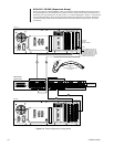
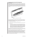
During normal startup, the diagnostic screen on the monitor (attached to the VGA output of the CPS-
see Figure 1-11) reflects successful hot switch initialization. Likewise, the system window of the PC
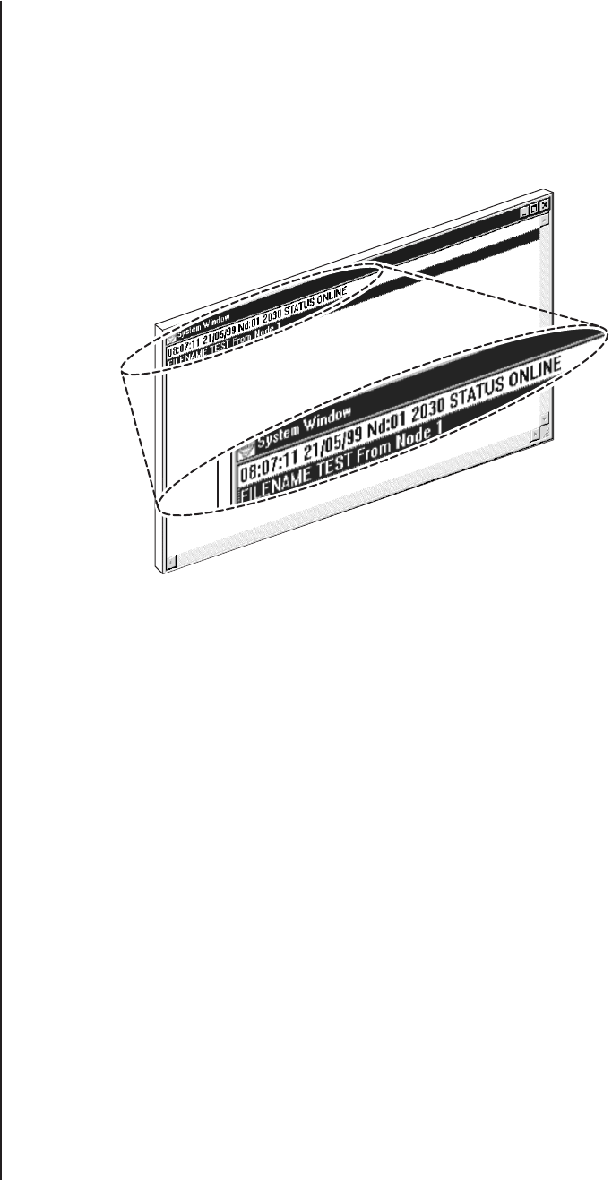
with MGR that is attached to the COM 1 output port of the CPS reflects the online status of the sys-
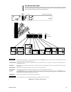
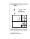
tem node (see Figure 3-1 below), but gives no additional information. In fact, the system window indi-
cates nothing amiss even if only one of the two available CC1s boots, and comes online successfully.
Although the system window reflects the status of the CC1 currently in control, it is not the tool of
choice for information regarding hot switch operation. To the MGR, hot switch operation is essentially
transparent.
Figure 3-1. System Window Online Status
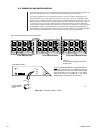
On the other hand, diagnostic screen displays, in addition to those associated with initialization, are
useful (see Figure 2-5). Diagnostic screen information, combined with LED activity, are the primary
sources of information on the status of hot-switch interfaced systems. Operationally, the diagnostic
screen supplies the following information:
1. It reflects the status of the controlling CC1 (if DIP switch 1-2 is ON**)
2. If DIP switch 1-2 is OFF, it reflects the status of the last selected CC1 (normally operator-selected
via the KVD button).
** This does not prevent the operator, if he wants, from viewing the diagnostic screen of the
non-controlling CC1. If the diagnostic view is changed by the operator to the non-controlling
CC1, that view will remain on-screen until an event occurs that updates system parameters
or until the operator changes the view back to the original, controlling CC1. The default DIP
switch setting is meant to automatically switch the diagnostic monitor to view the currently
active CC1 in the event a changeover occurs. A changeover is an HS-controlled event that
occurs because one of the CC1s is no longer operational. The result is an HS system error
that is accompanied by an audible alarm tone and a visual LED FAULT light.
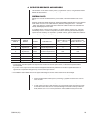
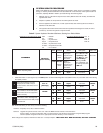
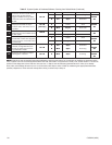
The most important area of the diagnostic screen to watch is located in the lower right-hand portion of
the display. There, you can read off the current mode of operation, which CC1 is in control, and the
software version of the system executable. These items are highlighted in Table D.
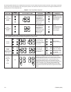
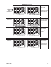
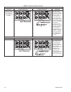
Diagnostic screen displays change as the result of direct operator action or because of automatic HS
response to system failure. Table D addresses those changes. Table D is similar to Table B, except
that in Table D, diagnostic screen display information, rather than LED activity, is related to the
implementation of the function listed in the left-hand column. The starting point is the diagnostic
display for default initialization. The diagnostic screens for both the A- and B-side matrix switches are
shown. The screen seen during normal default operation is the one associated with the controlling
switch (unless you opt to view the non-controlling diagnostic by pressing the appropriate KVD button).
That is why both diagnostic screens are illustrated.
20071