


C578M-A (4/05) 35
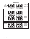
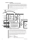
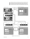
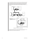
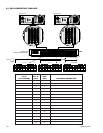
Interfacing network nodes with a hot switch (illustrated in Figure A4-2) can be extended to include the
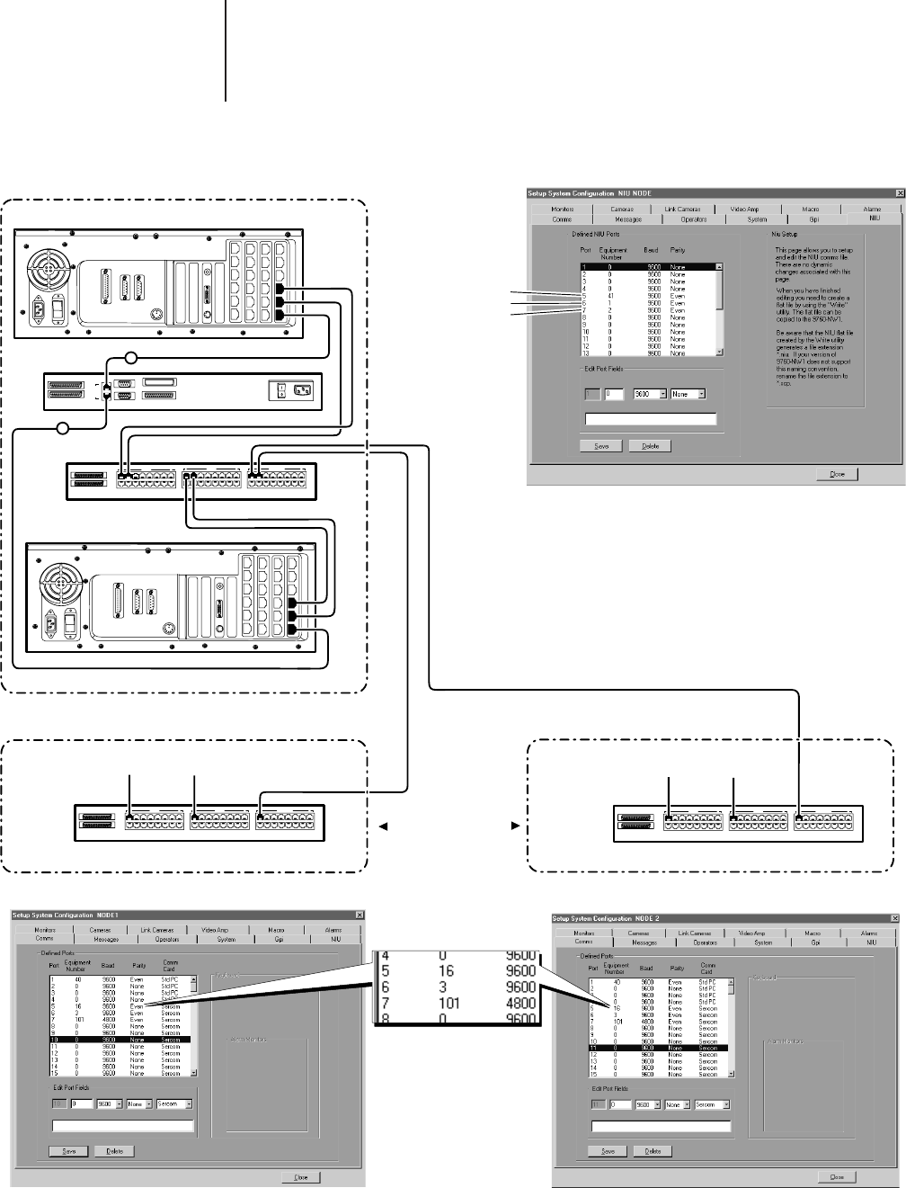
NIU itself. Figure A4-3 keeps the same node structure shown in Figure A4-2, except that now a hot
switch interfaces the NIU. Note that the equipment numbers for hot switches contained in the respec-
tive port definition files for the NIU and the Nodes themselves are different. These are equipment
numbers chosen for that specific configuration in order to differentiate between a hot switch hooked to
a controlling Network NIU from one connected to a regular node (interfacing CC1s) within a network.
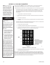
THE EQUIPMENT # FOR THE HOT
SWITCH CONNECTED TO THE NIU
IS 41.
THE EQUIPMENT # S FOR NODE 1
AND NODE 2 CONNECTED TO
PORTS 6 AND 7 OF THE NIU, ARE
EQUIPMENT #1 AND #2,
RESPECTIVELY.
NIU A
COM 1 COM 2
PRINTER
1 CC1 A 8 1 CC1 B 8 1 EQUIPMENT 8
IN
OUT
A
B
COM 2
COM 1
LOGGING PRNTER
IN
OUT
120-240 VAC 50/60 Hz
C
C
1
NIU B
COM 1 COM 2
PRINTER
1 CC1 A 8 1 CC1 B 8 1 EQUIPMENT 8
IN
OUT
1 CC1 A 8 1 CC1 B 8 1 EQUIPMENT 8
IN
OUT
PORT 5
PORT 6
PORT 7
PORT 7
PORT 6
PORT 5
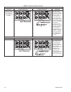
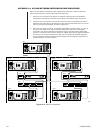
FIGURE A4-2 NODES
(PARTIAL REPRESENTATION)
9700 NIU NETWORK COMMS FILE (NIU TAB)
9700 NIU NETWORK CPU NODE
9700 NIU NETWORK NODE 29700 NIU NETWORK NODE 1
COMMS FILE FOR NODE 1
COMMS FILE FOR NODE 2
THE EQUIPMENT # FOR THE HOT
SWITCH CONNECTION TO PORT 5
ON EACH RESPECTIVE NODE IS 16.
THE EQUIPMENT # FOR THE NIU
CONNECTION TO PORT 6 ON EACH
RESPECTIVE NODE IS 3.
CM9760-SEU
HOT SWITCH
CM9760-CCC
HOT SWITCH
CM9760-SEU
HOT SWITCH
CM9760-SEU
HOT SWITCH
A
B
FROM
CC1 A
FROM
CC1 B
FROM
CC1 A
FROM
CC1 B
20074
Figure A4-3. Hot Switch Interfaced NIU