6 C578M-A (4/05)
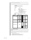
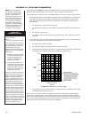
9760 HS COMMUNICATIONS
PARAMETERS
CC1 to HS Interface:
(Comm Parameters)
Equipment # 16
Baud Rate 9600
Parity EVEN
NIU to HS Interface:
(Comm Parameters)
Equipment # 41
Baud Rate 9600
Parity EVEN
20052
SECTION 1.0: INTRODUCTION
1.1 HS DEFINED
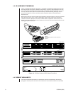
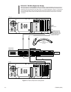
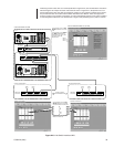
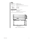
The CM9760-HS (Hot Switch) provides single-node, switching control between two CM9700-CC1
matrix switches. The default HS package consists of three subunits*, interconnected via in out, DB37,
male-to-male, molded cables that form a common bus for the subunits. These units provide the
interfaced system with operational redundancy.
Failure of the controlling matrix switch (designated the Master) passes control to the backup (designated
the Slave). Conversely, if the Slave unit fails, control remains with the Master unit. Any system failure
generates a system error that lights the FAULT LED (visual), and turns on an accompanying audible tone.
The audible signal is automatic unless turned off by DIP switch 1-1 (see Figure 2-4, DIP Switch
Configuration)
.
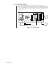
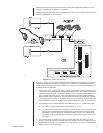
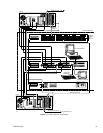
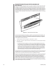
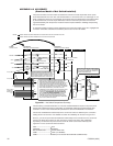
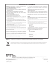
Figure 1-1 depicts the basic physical relationship between the HS, the interfaced CC1s,
and the external devices connected to the CPS and SEU output ports.
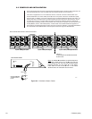
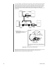
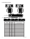
* The Serial Expansion Unit (SEU) is one of these units. However, it varies in number from one
(default), up to a possible eight units, depending on system configuration. Additional SEU units are
physically added to the hot switch via the HS common bus. Two SEU units are needed to interface a
fully populated CC1 (four Sercom cards containing a total of 32 ports). Future development may
require more than 32 Sercom ports to be interfaced. When that happens, SEU units (up to eight
total) can be added to the common bus to accommodate the increase in Sercom port population.
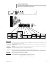
Figure 1-1. HS Block Diagram
Diagnostic equipment connected to CPS output ports display the status of HS health. Other devices,
connected to SEU output ports are under CC1 A or CC1 B control. For this reason, the interfaced
matrix switches must be hardware-software clones of each other in order for either to control the
same set of devices and to ensure a smooth transfer if a control transition (changeover) occurs.
Matrix switch equality is assured in the following manner:
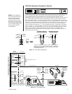
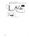
• Both switches must physically interface the HS in the same way. All cables and connections on
the A-side, switch-to-HS interface, are duplicated on the B-side. Basic interface requirements are
discussed in installation subsection
2.1 Physical
. Additional installation issues, beyond basic
setup, are discussed in
Section 4.0
Appendices.
• The physical equivalence of the matrix switches is likewise mirrored in their respective software
configuration file sets (Comms, Monitor, Camera, etc.) that are used to initialize and operate
each switch. Both sets must be identical.
Refer to the CM9700-MGR Getting Started Software Guide, on-screen help, or Online Help for
information about programming configuration files.
NOTE:
For those familiar with device attachment to 9700 Systems, a convenient reference box
is provided in the left margin that lists the communication parameters for hot-switch-interfaced
nodes (CC1 to HS), and for hot-switch-interfaced NIUs (NIU to HS). Refer to
Appendix
4.4, HS
and Networked Interfaced Configurations
, for more information.
IMPORTANT NOTE:
Users upgrading from previous hot switch models should consult
Appendix
4.2 HS Update (Previous Model of Hot Switch Installed)
, where important differences
between previous and current models are highlighted.
HS CONTROL
DIAGNOSTIC
PERIPHERAL
EXTERNAL
EXPANSION
CC1 A
CC1 B
HS
CCC
INPUT
CPS
OUTPUT
INPUT
AB C
INPUT
SEU
OUTPUT
INPUT
AB C
20057