C578M-A (4/05) 21
SECTION 3.0: OPERATION
3.1 PRELIMINARY REMARKS
There are two modes of HS operation. One is termed the synchronous mode and the other, the asyn-
chronous mode. Synchronous mode, of course, is the desired mode of operation. It is the optimal
mode of operation and the one the HS is designed to operate under. It is also the default mode of
operation and the only mode that provides proper backup to the system. The asynchronous mode,
on the other hand, is the mode the system reverts to (from synchronous mode) when a system error
occurs, for whatever reason. It is important to point out, however, that even in asynchronous mode,
the system is still up. In that sense, the asynchronous mode is also a successful mode because it
means that the HS successfully passed control to the working CC1 and that the interfaced system is
still operational. Once faults are corrected, the operator can manually return the system to its de-
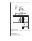
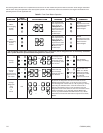
signed optimal, default configuration. This process, among others, is discussed in detail in Table E.
3.2 TERMS AND DEFINITIONS
The following terms are used extensively in the next few sections. We list a working definition of each
term to reduce confusion about their meaning when used in conjunction with the hot switch.
Synchronous – A hot switch operational mode that is the primary, default mode of HS operation. It
normally occurs at the end of a successful start-up. Once enabled, synchronous-mode control can be
switched from one matrix switch to the other by pressing the appropriate CC1 A or CC1 B button once.
Asynchronous – A hot switch operational mode in which the side in control is not synchronized with
the other side. It occurs as a result of any of the following:
1. A CC1-generated failure report to the HS. The HS FAULT LED is lit.
2. Manual intervention by an operator via front panel switches (pressing and holding CC1 A or
CC1 B button for two beeps). The HS FAULT LED is not lit.
3. A CC1 failure detected by the HS that one of the two CC1s is not operational. FAULT LED is lit.
When asynchronous mode is entered, the following may occur (dependent on the state of the system
at the time the action occurs):
1. A snapshot of the current state of the primary CC1 (if it has failed) is made and passed on to the
backup CC1.
2. The auto-changeover sequence is initiated and control is passed to the backup CC1, which is
automatically put into asynchronous mode.
3. If the backup fails, control remains with the primary Master unit. It is automatically put into asyn-
chronous mode.
Synchronization – An ongoing dynamic process wherein the current camera-monitor-user status
of the primary (Master or control side) is continually updated to the secondary (Slave or back-up)
side. The internal dynamics of the process is not under user control.
Changeover – A word that describes the automatic process of passing from synchronous to asyn-
chronous or from asynchronous to asynchronous mode because of the failure of either CC1 (primary
or backup), while in synchronous or asynchronous mode, respectively. Of course, the appropriate DIP
switch settings must be configured to allow this.
The HS implements an automatic changeover for the following reasons:
1. There is a primary COM failure with either CC1.
2. A secondary problem with either CC1 that results in its failure.
Either of the above results in the system FAULT LED being lit.
Additionally, changeovers can be manually initiated by the operator (see Table B). The FAULT
LED is not lit.


