


20 C578M-A (4/05)
2.2 POWER-UP AND INITIALIZATION
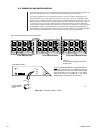
Once configuration files have been programmed and loaded and all connection cabling has been run,
then the associated CC1s, the hot switch and all connected devices can be turned on.
The order of equipment turn-on is immaterial; however, if the HS is turned on before either CC1
finishes initialization, the online LEDs (A and B) on the front panel of the CCC will alternate rapidly
back and forth. In addition, if the HS is ON and one CC1 finishes initialization ahead of the other, you
might notice that it will temporarily be made the Master and the mode will be Asynchronous. This is
no cause for concern; it is normal. When the entire system finally initializes, the CCC determines
whether default operating conditions are possible, and, if they are, the system will enter synchronous,
A-Side (Master) control, with B-Side (Slave). A visual check of successful initialization appears on
appropriately connected diagnostic monitors; however, the primary indicator of successful initialization
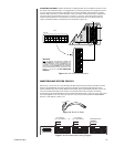
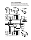
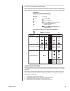
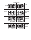
is a visual check of the LEDs located on the front panel of the CCC. Figure 2-5 illustrates this.
Figure 2-5. Initialization Status, Default
INITIALIZATION AND DEFAULT STATUS INDICATORS
A-SIDE DIAGNOSTIC SCREEN
B-SIDE DIAGNOSTIC SCREEN
DEFAULT:
A-SIDE MASTER SYNCHRONOUS MODE
B-SIDE SLAVE
CCC FRONT PANEL
FAULT
A
B
LEDs ALTERNATE
AS INDICATED IN
NOTE.
PWR
SYSTEM 9760
System : Sending Full Synch
System : Full Synch Complete
System : Full Synch Complete On Slave
NOTE: LEDs A AND B ALTERNATE (OR PING-PONG) BACK
AND FORTH. WHEN LED A IS ON, LED B IS OFF FOR THE
SAME PERIOD OF TIME. THE LED FOR THE SIDE HAVING
MASTER CONTROL (IN THIS CASE, A) IS ON ABOUT
FOUR TIMES AS LONG AS THE B LED. IF THE B-SIDE
WERE MASTER, THE OPPOSITE WOULD OCCUR.
FAULT
A
B
20070