


C578M-A (4/05) 9
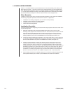
LOGGING PRNTR
A
B
A
B
OUT
IN
120-240 VAC 50/60 Hz
C
C
1
20053
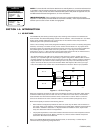
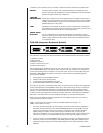
THE CCC (Computer Changeover Control)
The CCC subunit is the heart of the hot switch. Data connections between the interfaced CC1s
(matrix switches) and the HS are located here. Two connector types that correspond to two
communication types for the data line to the CCC are provided: RJ-45 or DB9. You can use either, but
the connector type chosen determines the communication protocol you must use and vice versa.
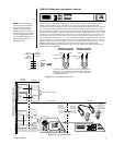
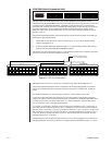
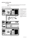
Both are illustrated in Figure 1-5. In the top portion of Figure 1-5, the RJ-45 data line connection (one
from each switch) is shown. If RS-422 communication is chosen, the data cable from a port on matrix
switch CC1 ‘A’ (an RJ-45 Sercom port, usually port 5) is run to the RJ-45 CC1 A port on the CCC. A
similar cable is run from CC1 ‘B’ to the RJ-45 CC1 B port on the same CCC. These cables are re-
versed or “flipped” and utilize pins 1, 2, 7, and 8 as depicted in Figure 1-4. Alternately, in the bottom
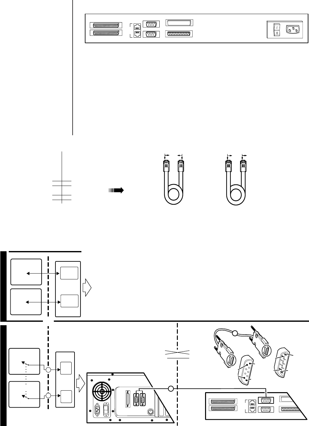
portion of Figure 1-11, the RS-232 data line connection is shown. A DB9 cable is run from either the
COM 1 or COM 2 port (on the respective CC1 ‘A’ or CC1 ‘B’ switch) to the appropriate (CC1 A or B)
DB9 port on the CCC. The cables for the DB9 data connection runs are not supplied. Pelco
recommends that RS-422 communication be used whenever possible. The cables for the RS-422
data connections are provided.
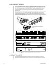
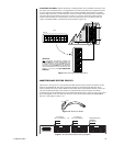
Figure 1-4. Data Cable Identification
Figure 1-5. Data Cable Wiring
NOTE:
When upgrading to
the current hot switch from a
previous model, note the
following. The data cable,
previously used to connect
RJ-45 port 5 on each switch
and the corresponding COM 1
[S1] and COM 2 [S2] ports on
the hot switch, cannot be
substituted here.
PIN 5
PIN 9
PIN 6
PIN 1
PRINTER
COM 1 COM 2
DB9/F-M
CC1-CCC (RS-232)
COM 1/COM 2 (CC1) TO
DB9 A/B (CCC)
CROSSOVER CABLE
1
CC1 A OR B
CM9760-CCC (REAR VIEW)
PIN 1
PIN 6
PIN 9 PIN 5
1
CM9700-CC1
COM PORT DATA
CONNECTION
OUTPUT (DB9)
LOGGING PRNTR
A
B
A
B
OUT
IN
C
C
1
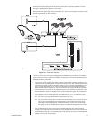
SEE FIGURES 1-11 AND 2-1
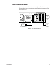
COMMUNICATION PARAMETER CONNECTIONS
EITHER COM 1 OR COM 2 (ON THE MATRIX SWITCH SIDE)
CAN BE USED. IF COM 1 IS CHOSEN, BOTH SWITCHES
MUST USE COM 1, OR ELSE BOTH MUST USE COM 2.
RS-232 AVAILABLE
RS-422 RECOMMENDED
MATRIX
SWITCHES HOT SWITCH
CM9760-CCC
CM9700-CC1 A
CM9700-CC1 B
RJ-45
SERCOM
PORT
RJ-45
SERCOM
PORT
RJ-45
A
RJ-45
B
CM9700-CC1 A
CM9700-CC1 B
COM 1
OR
COM 2
COM 1
OR
COM 2
DB9
A
DB9
B
MATRIX SWITCHES HOT SWITCH
CM9760-CCC
1
1
OR
PIN 2 (RX) PIN 2 (RX)
PIN 3 (TX) PIN 3 (TX)
PIN 5 (GND) PIN 5 (GND)
CM9760-CCC
A- OR B-SIDE
INPUT (DB9)
FLIPPED CABLE
OR
REVERSE CABLE
STRAIGHT CABLE
OR
PARALLEL
BROWN BROWN
BROWN BROWN
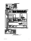
TO IDENTIFY A CABLE TYPE, PHYSICALLY ORIENT THE RJ-45 CABLE AS
DEPICTED IN THE ILLUSTRATION. ORIENT THE CABLE CONNECTORS
SIDE-BY-SIDE, TAB SIDE DOWN. USE THE COLOR-RUN OF THE WIRES
TO DETERMINE CABLE TYPE.
18
27
72
81
COMPARED “COLOR RUN”
IS IN OPPOSITE DIRECTION
FLIPPED
VS
STRAIGHT
CABLE
WIRING
COMPARED “COLOR RUN”
IS IN SAME DIRECTION
9760-CCC
A- OR B-SIDE
INPUT (RJ-45)
9700-CC1
SERCOM PORT
DATA
CONNECTION
OUTPUT (RJ-45)
(SEE FIGURE 2-1)