


C578M-A (4/05) 17
9700-CC1 TO CPS (Diagnostic Group)
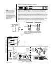
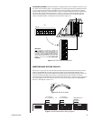
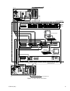
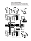
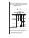
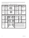
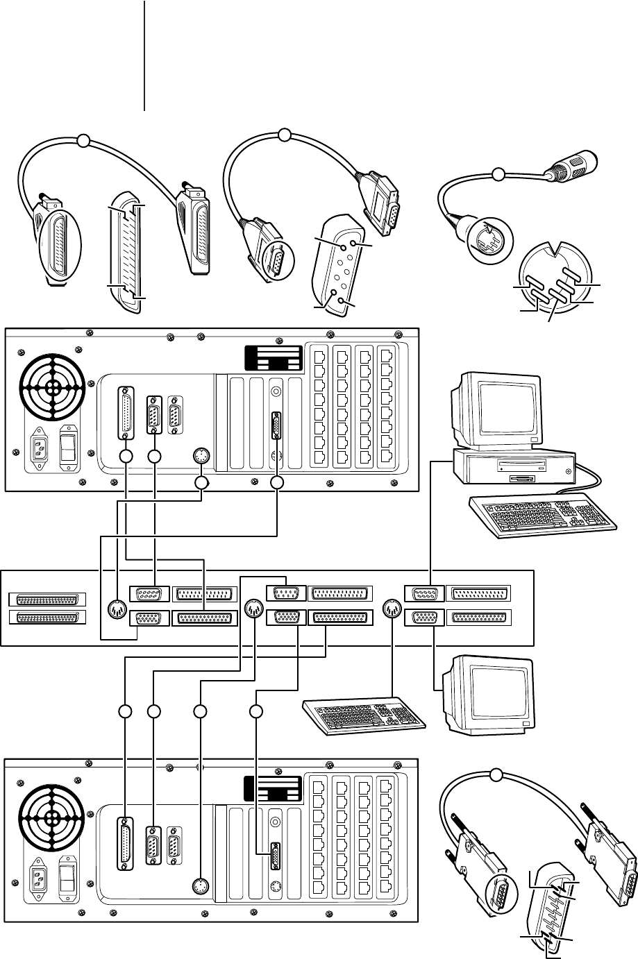
The connection points for diagnostic and monitor tools for hot switch and system status are shown in
Figure 2-2. Note that COM 1 on either CC1 (the normal connection point for the PC w/MGR in a
stand-alone CC1 configuration) is run to the appropriate COM 1 input connector on the CPS. COM 1
output on the CPS is reserved for the PC w/MGR connection. If a CC1 COM port on the switch is
defective, the other port can be used, but you must still connect to COM 1 on the CPS. Moreover, you
must follow suit on any change in physical COM port configuration in the duplicate CC1. In addition, any
port changes must be reflected in the COMMS file.
Figure 2-2. Diagnostic Group, Cabling Detail
CC1 A CC1 B EQUIPMENT
COM 1 COM 2
VGA PRINTER
COM 1 COM 2
VGA PRINTER
MODEL
SERIAL
VOLTS WATTS
FREQ AMPS
MODEL
SERIAL
VOLTS WATTS
FREQ AMPS
DB25/M-M
CC1-CPS
PRINTER-PRINTER
(NOT SUPPLIED)
DB9/F-F
CC1-CPS
COM 1-COM 1
NULL MODEM CABLE (SUPPLIED)
10 FT (3.05 M)
5-PIN DIN/M-M
CC1-CPS
AT KBD-AT KBD (SUPPLIED)
10 FT (3.05 M)
DB15/M-M
CC1-CPS
VGA-VGA (SUPPLIED)
10 FT (3.05 M)
DIAGNOSTIC MONITOR
DIAGNOSTIC KEYBOARD
PC WITH 9700 MGR
PRINTER
COM 1 COM 2
PIN 14 PIN 1
PIN 25
PIN 13
1
2
3
PIN 9
PIN 5
PIN 6 PIN 1
PIN 3
PIN 5
PIN 2
PIN 1
PIN 4
4
PIN 11
PIN 1
PIN 6
PIN 5
PIN 10
PIN 15
COM 1 COM 2
PRINTER
1
2
21
3
3
4
4
CC1 A
CC1 B
CPS
AT
KBD
AT
KBD
AT
KBD
OUT
IN
COM 1 COM 2
VGA PRINTER
**
**
** SEE FIGURE 1-6 FOR COM 2 CABLING OPTIONS