


34 C578M-A (4/05)
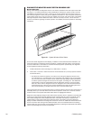
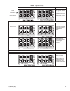
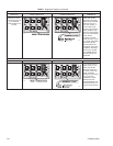
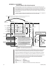
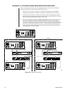
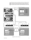
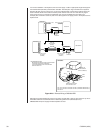
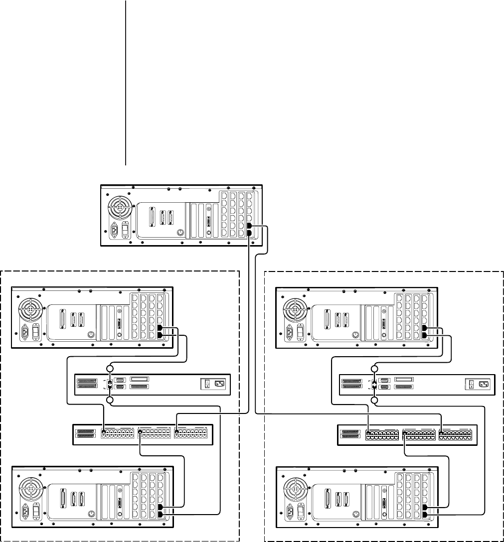
Figure A4-2. HS-NIU Connections
1 CC1 A 8 1 CC1 B 8 1 EQUIPMENT 8
CC1-B
SEU
CC1-A
CCC
IN
OUT
A
B
NIU
NODE 1
A
B
LOGGING PRNTER
A
B
CC1-B
SEU
CC1-A
CCC
NODE 2
A
B
LOGGING PRNTER
1 CC1 A 8 1 CC1 B 8 1 EQUIPMENT 8
COM 1 COM 2
PRINTER
B
A
IN
OUT
IN
OUT
120-240 VAC 50/60 Hz
COM 1 COM 2
PRINTER
120-240 VAC 50/60 Hz
COM 1 COM 2
PRINTER
COM 1 COM 2
PRINTER
COM 1 COM 2
PRINTER
C
C
1
IN
OUT
A
B
C
C
1
20073
APPENDIX 4.4 HS AND NETWORK-INTERFACED CONFIGURATIONS
Below are node-specific connections of NIU configurations, where each node is hot-switched.
Note the following points, which are also reflected in Figure A4-2:
1. Each CC1 port connection to the HS (on its respective node) stays at port 5 (standalone
configuration) while the NIU connection (via the SEU) is connected to port 6 on each CC1.
2. The port 6 Sercom connection of the NIU from each CC1 node (in ascending node order) is
attached to the system NIU (in ascending port order), starting at NIU Sercom-port 5. It arrives
there via routing through the SEU, as shown in Figure A4-2.
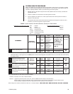
3. Each node, with respect to the HS, is essentially independent of the NIU. That is, any node, at
any time, can be taken off the network without bringing the network down. Node-specific
procedures, such as those described in this manual, can be performed without affecting NIU
operation. It should be noted, however, that the PC w/MGR, along with the diagnostic keyboard
and monitor are normally connected to the “NIU” CC1. This means that available diagnostic
screen information is less informative than that available when the diagnostic peripherals are
attached directly to the node in question.