


C578M-A (4/05) 7
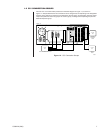
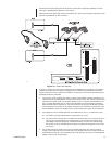
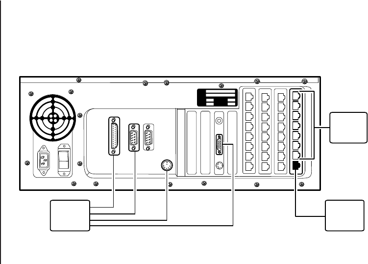
Figure 1-2. CC1 Connection Groups
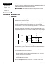
1.2 CC1 CONNECTION GROUPS
The rear view of a matrix switch (referenced in the block diagram of Figure 1-1) is shown in
Figure 1-2. Outputs destined for HS connections can be categorized, corresponding to the designated
functions of the subunits to which they are attached on the hot switch. For discussion purposes, these
outputs are partitioned into three groups: the Control group, the Diagnostic-Peripheral group and the
External Expansion group.
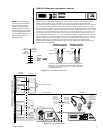
CC1 A
TO THE
CPS
TO THE
CCC
TO THE
SEU
DIAGNOSTIC-PERIPHERAL GROUP
CONTROL
GROUP
EXTERNAL
EXPANSION
GROUP
PRINTER
COM 1 COM 2
MODEL
SERIAL
VOLTS WATTS
FREQ AMPS
20058